Detection apparatus, detection system, and moving object

Active Publication Date: 2017-05-04
SEIKO EPSON CORP
View PDF19 Cites 8 Cited by
  • Summary
  • Abstract
  • Description
  • Claims
  • Application Information

AI Technical Summary

Benefits of technology

[0009]An advantage of some aspects of the invention is to provide a detection apparatus, a detection system, and a moving object

Problems solved by technology

In such a self position estimation, there is a problem that there is a case where the self position of the moving object cannot be always accurately estimated depending on a point where the sensor is arranged on the moving object.
However, even when an estimation method is applied to a shopping cart, the self position cannot be accurately estimated.
In additio

Method used


Image

  • Detection apparatus, detection system, and moving object
  • Detection apparatus, detection system, and moving object
  • Detection apparatus, detection system, and moving object

Examples


Embodiment Construction

[0054]A preferred embodiment of the invention will be described below in detail. The embodiment of the invention described below does not improperly limit the contents of the invention described in the appended claims, and it is not always true that all of configurations described in the embodiment are essential as solving means of the invention.

1. Detection Apparatus and Detection System

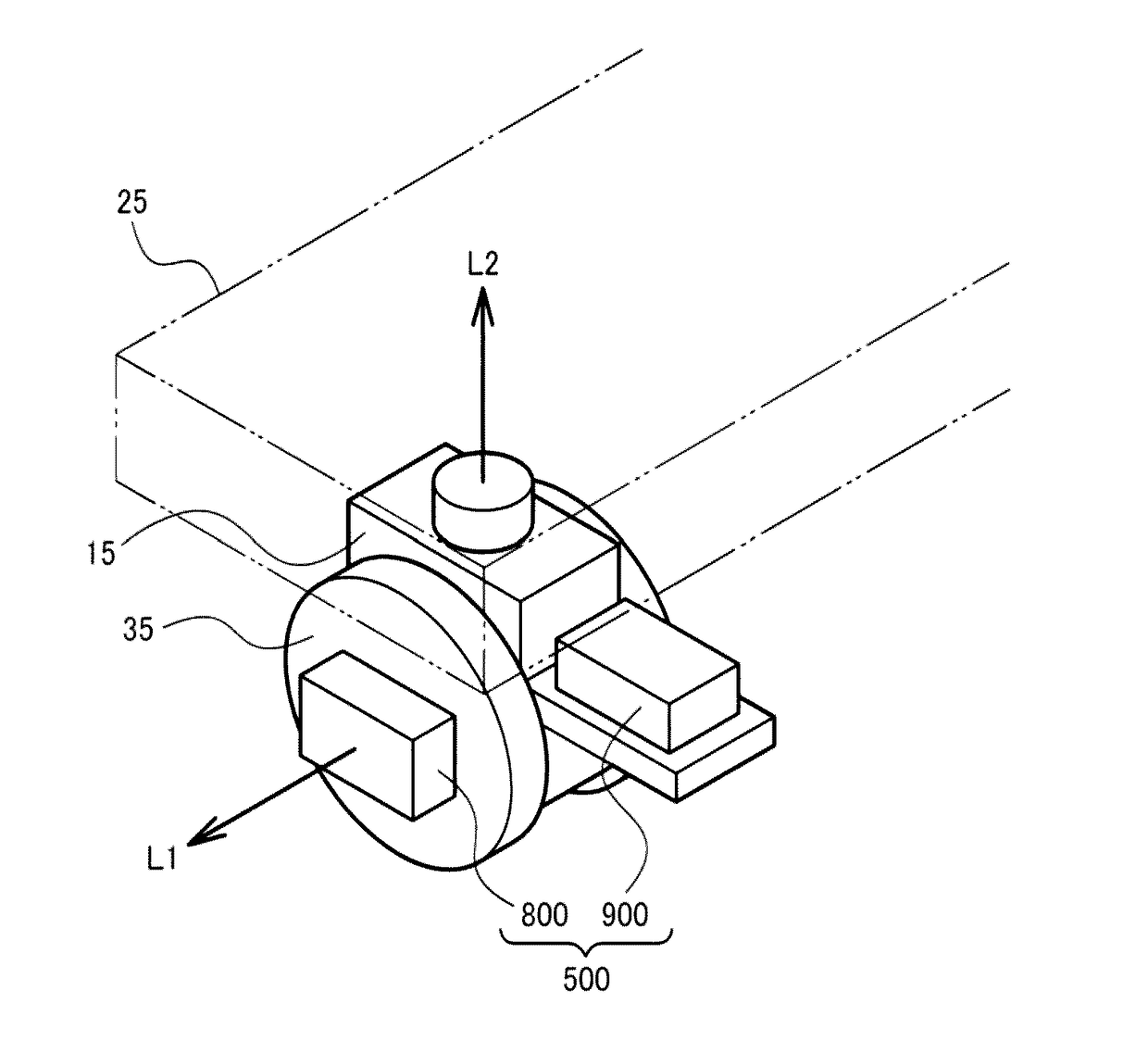
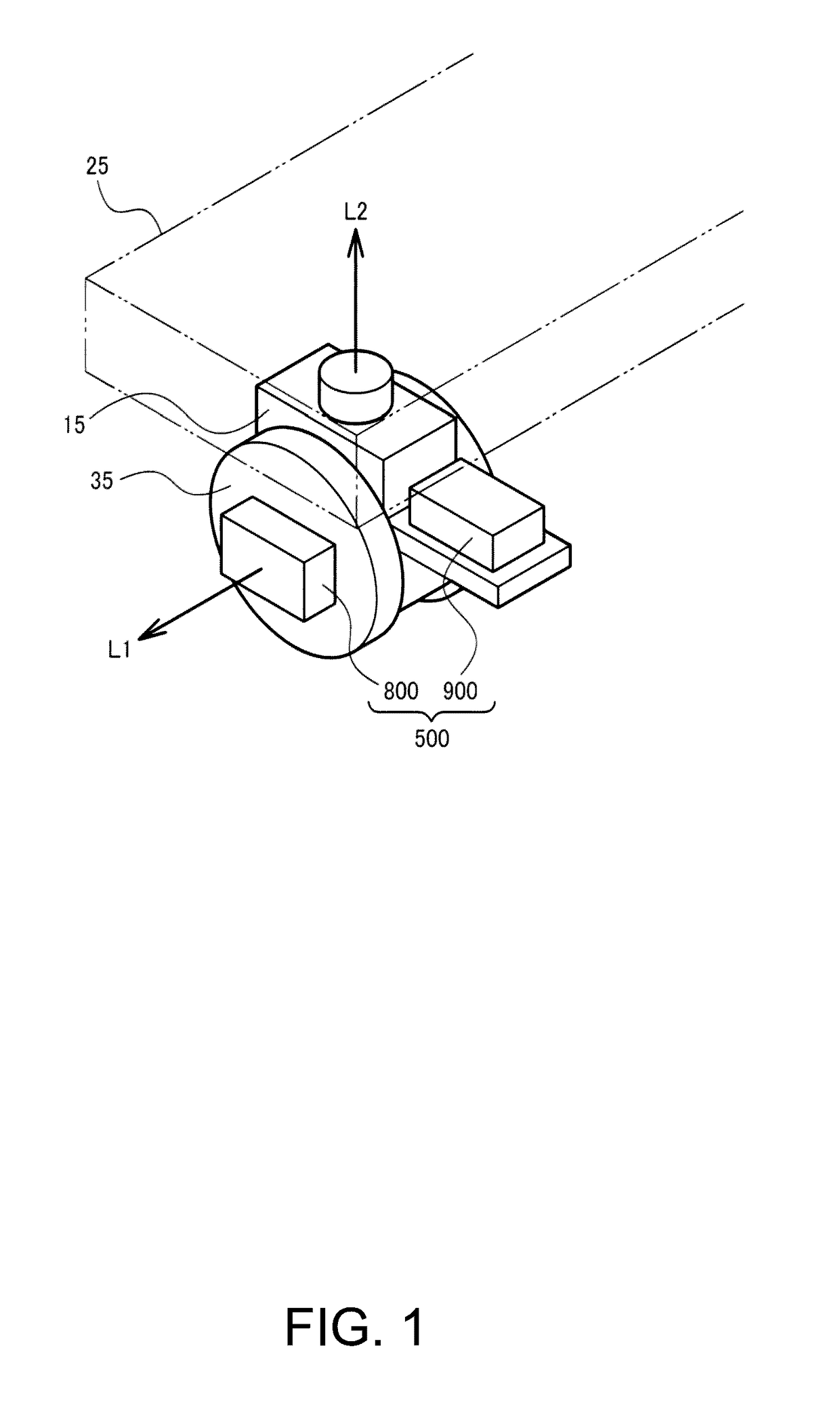
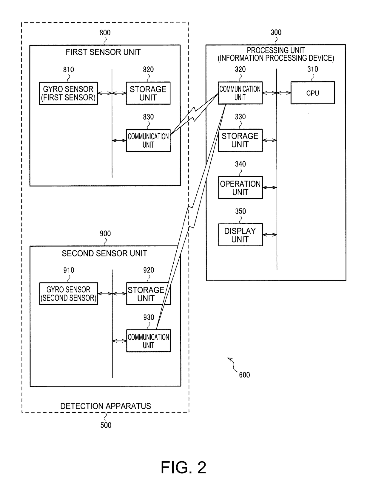
[0055]FIG. 1 illustrates a configuration example of a detection apparatus 500 according to the present embodiment. FIG. 2 illustrates configurations of the detection apparatus 500 and a detection system 600. The detection system 600 includes the detection apparatus 500 and a processing unit 300. The detection apparatus 500 includes a first sensor unit 800 and a second sensor unit 900. The first sensor unit 800 includes a gyro sensor 810 (first sensor), a storage unit 820, and a communication unit 830. The second sensor unit 900 includes a gyro sensor 910 (second sensor), a storage unit 920, and a co...


PUM


Abstract

A detection apparatus includes a first sensor for detecting rotation information of a wheel of a moving object; a second sensor for detecting angular velocity information of a rotation in a yaw axis of the wheel or angular information as yaw rotation information; and a storage unit for storing the rotation information and the yaw rotation information to be output to a processing unit for obtaining positional information of the moving object based on the rotation information and the yaw rotation information.

Description

BACKGROUND[0001]1. Technical Field[0002]The present invention relates to a detection apparatus, a detection system, and a moving object.[0003]2. Related Art[0004]As a method for estimating a self position of a moving object in a case where positional information cannot be obtained from outside of the moving object by a GPS or the like, a method called dead reckoning or odometry is known. In these methods, the self position of the moving object is estimated based on the outputs from various sensors provided in the moving object.[0005]For example, JP-A-2006-349399 discloses an azimuth measuring device for detecting a rotational angular velocity of the rotation about a vertical axis of a moving object and a rotational velocity of a drive wheel, and selecting any one of the rotational angular velocity rotating about the vertical axis of the detected moving object and the rotational angular velocity rotating about the vertical axis of the moving object to be estimated from the rotational...

Claims


Application Information

Patent Timeline
IPC IPC(8): G01C19/5776G01C21/12
CPCG01C21/12G01C19/5776G01C19/34G01C22/00G01C21/166G01C21/206
Inventor KURASHINA, TAKASHIMAKI, KATSUHIKOHANEDA, HIDEO
Owner SEIKO EPSON CORP
Why Eureka
Try Eureka