
Connector having locking of the lever for facilitating the connection

Inactive Publication Date: 2017-05-04
DELPHI INT OPERATIONS LUXEMBOURG S A R L
View PDF0 Cites 1 Cited by
  • Summary
  • Abstract
  • Description
  • Claims
  • Application Information

AI Technical Summary

Benefits of technology

The invention provides a connector that is shorter and more compact in the direction of coupling through a design where the lock and elastic tabs are arranged transversally in relation to the direction of coupling. This reduces the risk of rupture of the tabs and makes the lock more stable and robust when receiving pressure. Additionally, the tabs are symmetrically positioned to either side of the lock for greater stability and robustness. The design also allows for a displacement towards the housing with a component that is principally in translation.

Problems solved by technology

In certain cases, the maximum authorized dimensions for the connector are such that this type of configuration described in WO 2010 / 136832 is not acceptable.

Method used


Image

  • Connector having locking of the lever for facilitating the connection
  • Connector having locking of the lever for facilitating the connection
  • Connector having locking of the lever for facilitating the connection

Examples


Embodiment Construction

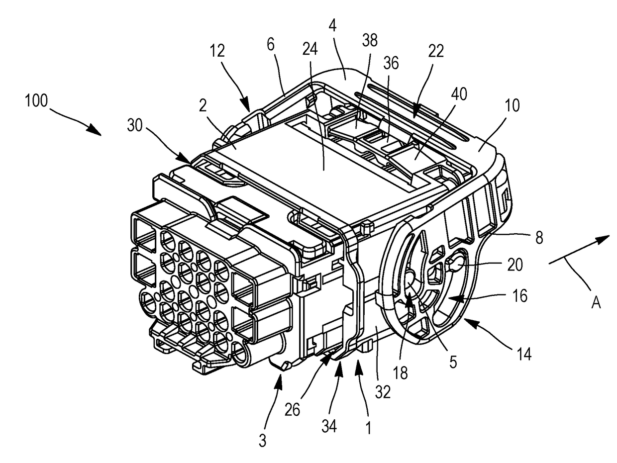
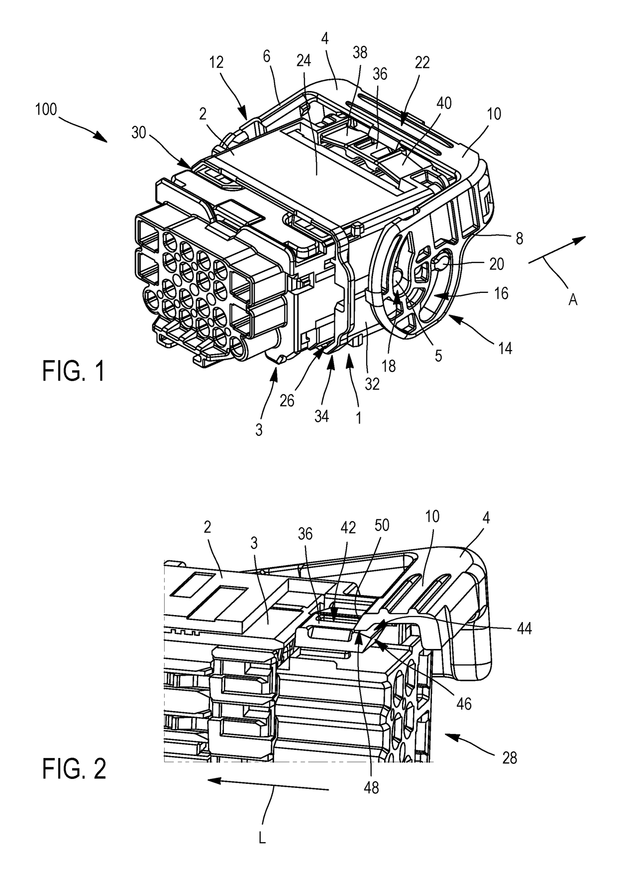
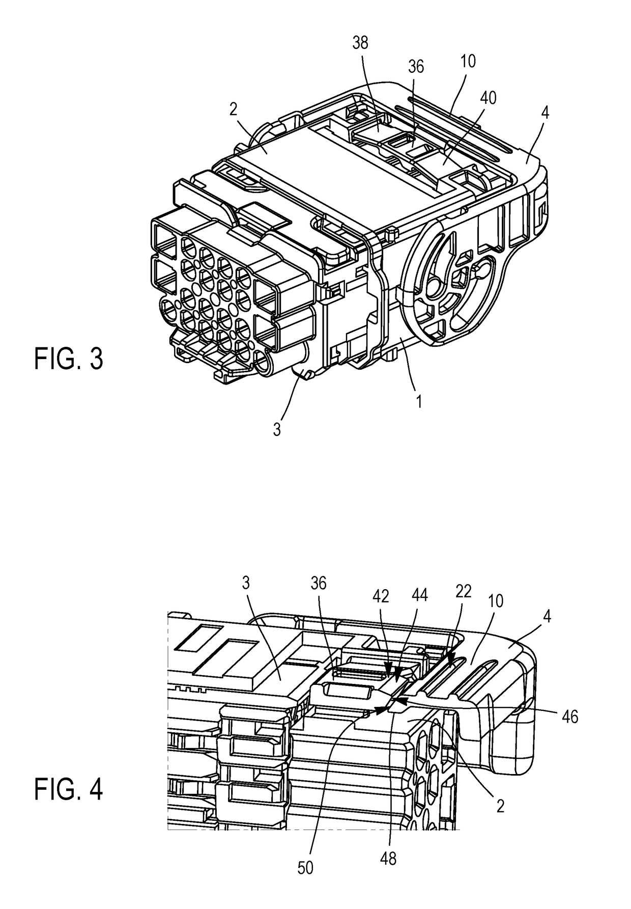
[0028]A non-limiting example of a connection assembly 100 depicted in FIG. 1 includes a connector 1 and a counter-connector 3. These are connectors that are used for automotive connector technology applications.

[0029]These are straight connectors, that is to say not elbowed, in which the cables (not depicted here) exit via opposite faces, being essentially parallel with each other and perpendicular to the direction of coupling A.

[0030]The connector 1 includes a housing 2 and a lever 4. It likewise includes female contacts or clips constituted by a metallic conductor, albeit not depicted here. Similarly, the counter-connector 3 includes male contacts or tongues (likewise not depicted in the figures) constituted by a metallic conductor.

[0031]The lever 4 includes two lever arms 6, 8 and a handle 10 connecting the two lever arms 6, 8 in order to form a “U”. Each lever arm 6 or 8 is integrally formed with a flange 12 or 14 situated at the other extremity of the lever arm 6 or 8 in relati...


PUM


Abstract

The invention relates to a connector having a lever for facilitating the connection. The connector comprises a housing on which a lever is rotatably mounted between an open position, in which a counter-connector may be coupled to the connector in one direction of coupling, and a closed position, in which the connector and the counter-connector are locked together. The lever is maintained in the closed position by a lock that is connected to the housing with the help of two tabs, each extending respectively from the lock towards the housing, in a direction perpendicular to the direction of coupling. In order to disengage the lever and the lock, the lock is displaced towards the housing by a translation perpendicular to the direction of coupling.

Description

CROSS-REFERENCE TO RELATED APPLICATION[0001]This application claims the benefit under 35 U.S.C. §119(a) of Patent Application No. 1560283 filed in the Institut National de la Propriété Industrielle (French Patent Office) on Oct. 28, 2015, the entire disclosure of which is hereby incorporated by reference.TECHNICAL FIELD OF THE INVENTION[0002]The invention relates to the field of connector technology, and in particular that of automotive connector technology.BACKGROUND OF THE INVENTION[0003]Connectors are used to transmit signals or electrical energy between cables, devices (computer, lighting, etc.) or motors. In particular, electrical connectors include electrical contacts in a greater or smaller number, or of a larger or smaller size. The contact force must be sufficiently high in order to ensure good electrical conduction between male and female contacts. For this reason, and in particular if contacts are of a relatively large size, for example as a result of being connected to a...

Claims


Application Information

Patent Timeline
IPC IPC(8): H01R13/629H01R13/627
CPCH01R13/62955H01R13/6273H01R13/62938H01R13/62933
Inventor GUILLANTON, MELANIELOAS, SYLVAIN
Owner DELPHI INT OPERATIONS LUXEMBOURG S A R L
Learn More