Insertion frame structure and housing using same

Active Publication Date: 2014-04-17
MITSUBISHI ELECTRIC CORP
View PDF44 Cites 2 Cited by
  • Summary
  • Abstract
  • Description
  • Claims
  • Application Information

AI Technical Summary

Benefits of technology

[0011]The insertion frame structure according to the present invention includes: a pair of primary members whose cross-sectional shapes are, at least partially, L shapes, and which are placed being separated by a predetermined distance such that the inner surface sides of the L shapes face to each other symmetrically with respect to a center line passing the midpoint of the predetermined distance; and a plurality of auxiliary members whose cross-sectional shapes are, at least partially, L shapes, and which are placed between the primary members. The primary members and the auxiliary members are joined with each other at their latch portions. The latch portions of the primary members each have a latch hole with a clearance shape. The latch portions of the auxiliary members each have a convex portion to be inserted into the latch hole. Each of the latch holes has a clearance with a larger dimension than a plate thickness t of the auxiliary member, and has, continuously from the clearance, a clearance with a dimension equal to the plate thickness t of the auxiliary member or smaller than the plate thickness t of the auxiliary member. Therefore, the positioning accuracy between the primary member and the auxiliary member is enhanced, and in addition, since the primary member and the auxiliary member are not easily detached, a latch member such as a rivet is not needed.
[0012]The other insertion frame structure according to the present invention includes: a pair of groove-shaped primary members whose cross-sectional shapes are, at least partially, angular U shapes, and which are placed being separated by a predetermined distance and facing to each other symmetrically with respect to a center line passing the midpoint of the predetermined distance; and a plurality of auxiliary members whose cross-sectional shapes are, at least partially, L shapes, and which are placed between the primary members. Th

Problems solved by technology

In addition, in the case of performing such welding, since thermal distortion due to welding occurs, r

Method used


Image

  • Insertion frame structure and housing using same
  • Insertion frame structure and housing using same
  • Insertion frame structure and housing using same

Examples


embodiment 1

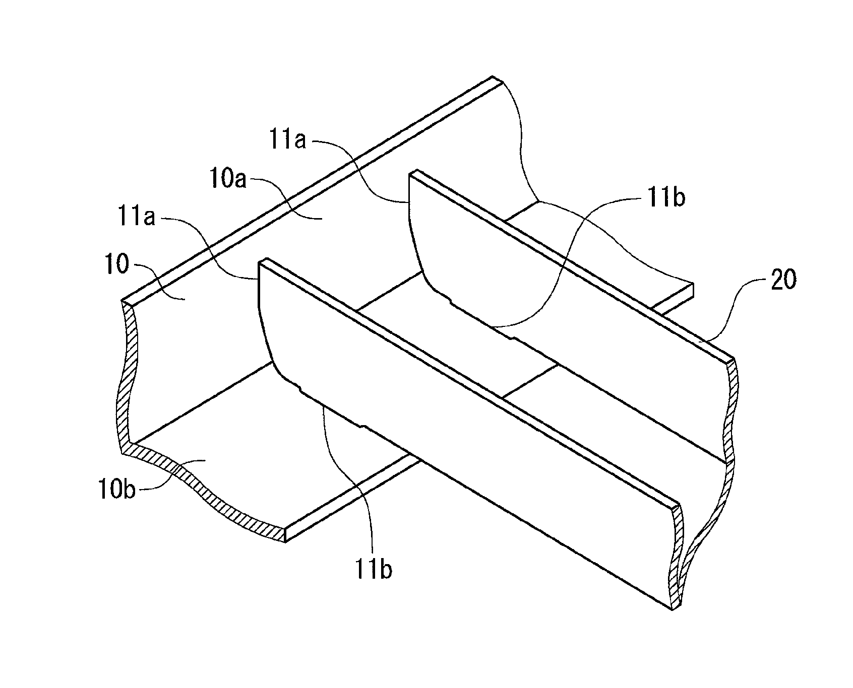
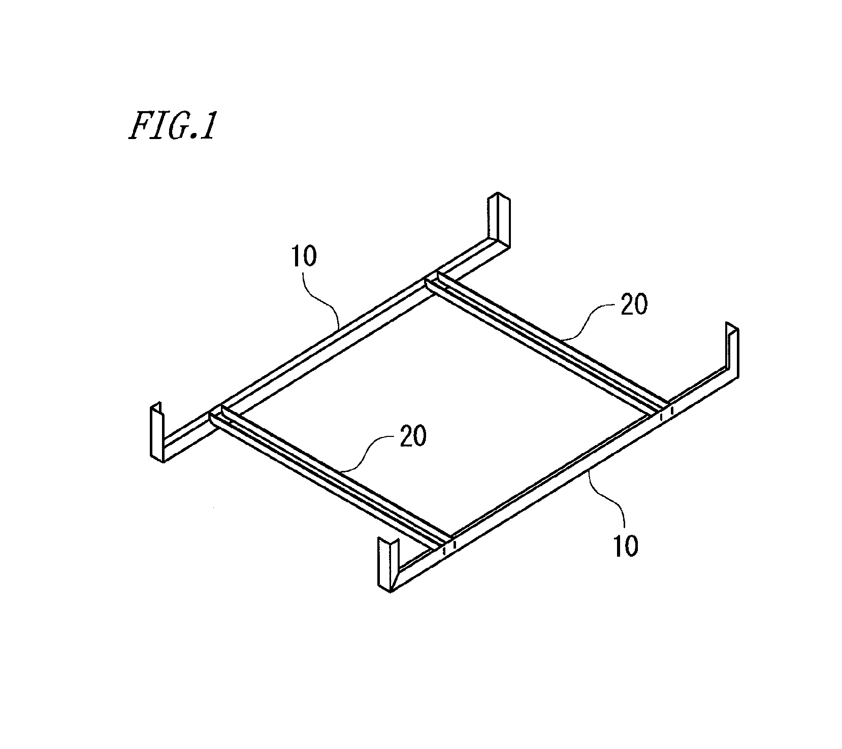
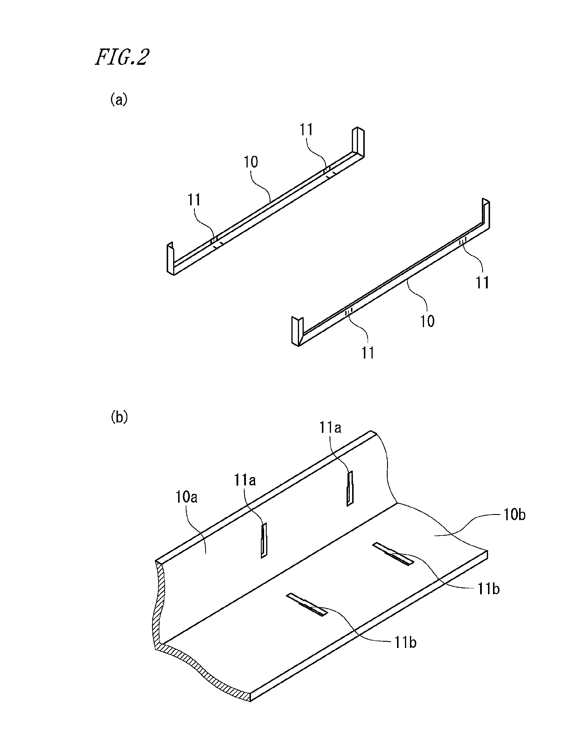
[0032]FIG. 1 is a perspective view showing an insertion frame structure according to embodiment 1 of the present invention. FIG. 2 is a perspective view showing a primary member in the insertion frame structure of embodiment 1. FIG. 3 is a perspective view showing an auxiliary member in the insertion frame structure of embodiment 1. FIG. 4 is a perspective view showing a joint portion in the insertion frame structure of embodiment 1. FIG. 5 is a perspective view showing an assembly process of the primary member and the auxiliary member in the insertion frame structure of embodiment 1. FIG. 6 shows a left side view (a) and a front view (b) of a latch portion of the auxiliary member, and a sectional view (c) showing the way of insertion into a latch hole of the primary member, in the insertion frame structure of embodiment 1. FIG. 7 shows a side view (a) and a plane view (b) of a latch portion of the primary member in the insertion frame structure of embodiment 1. FIG. 16 is a perspec...

embodiment 2

[0046]FIG. 8 is a perspective view showing an insertion frame structure according to embodiment 2 of the present invention. FIG. 9 is a perspective view showing a primary member in the insertion frame structure of embodiment 2. FIG. 10 is a perspective view showing an auxiliary member in the insertion frame structure of embodiment 2. FIG. 11 is a perspective view showing a joint portion in the insertion frame structure of embodiment 2. FIG. 12 is a perspective view showing an assembly process of the primary member and the auxiliary member in the insertion frame structure of embodiment 2. FIG. 13 shows a left side view (a) and a front view (b) of a latch portion of the auxiliary member in the insertion frame structure of embodiment 2. FIG. 14 shows a left side view (a), a plane view (b), and a right side view (c) of a latch portion of the primary member in the insertion frame structure of embodiment 2. FIG. 15 is a sectional view of the latch portions of the primary member and the au...

embodiment 3

[0060]In the above embodiments 1 and 2, the latch holes 11a, 11b, and 11c of the first latch portion 11 of the primary member 10 each have a clearance (t+β) larger than the plate thickness t of the auxiliary member 20, and have, continuously from this clearance, a clearance smaller than the plate thickness t of the auxiliary member 20. On the other hand, in embodiment 3, the latch holes 11a, 11b, and 11c of the first latch portion 11 of the primary member 10 each have a clearance (t+β) larger than the plate thickness t of the auxiliary member 20, and have, continuously from this clearance, a clearance equal to the plate thickness t of the auxiliary member 20.

[0061]Since the clearances of the latch holes 11a, 11b, and 11c of the first latch portion 11 of the primary member 10 are equal to the plate thickness t of the auxiliary member 20, the convex portions 21a, 21b, and 21c of the auxiliary member 20 can be easily pressed into the latch holes 11a, 11b, and 11c of the primary member ...


PUM


Abstract

To enhance the positioning accuracy between primary members and auxiliary members without need of latch parts such as rivets, an insertion frame structure includes: a pair of primary members having L-shaped cross-sections and placed with the L shapes facing to each other symmetrically; and several auxiliary members having angular U-shaped cross-sections between the primary members. The primary members and the auxiliary members are joined at latch portions. The latch portions of the primary members have clearance-shaped latch holes. The latch portions of the auxiliary members have convex portions to be inserted into the latch holes. Each latch hole has a clearance with a larger dimension than a plate thickness t of the auxiliary members, and continuously from the clearance, a clearance with a dimension smaller than the plate thickness t of the auxiliary members.

Description

TECHNICAL FIELD[0001]The present invention relates to an insertion frame structure assembled by fitting members into each other, and to a housing the insertion frame structure.BACKGROUND ART[0002]In the case where a shape steel with an H-shape or a groove shape or sheet metal is bent into an L shape or an angular U shape, and then such bent members are assembled to manufacture a frame structure, generally, these members are joined by welding. Upon this welding, in order to accurately adjust the positions of the members and improve the work efficiency of the welding, a special fixture and an exclusive welding technician are needed. In addition, in the case of performing such welding, since thermal distortion due to welding occurs, repair work such as distortion removal is needed. Thus, a problem of causing much labor and cost arises.[0003]In order to solve this problem, an insertion frame structure is proposed which is composed of a pair of primary members with an angular U shape and...

Claims


Application Information

Patent Timeline
IPC IPC(8): F16B7/20F16B5/10
CPCF16B5/10F16B7/20E04B1/5806E04B1/5818F16B7/0446F16B21/09E04B2/765E04B2/766E04B9/127Y10T403/46
Inventor HAYASHI, TOMOYUKIHASHIZUME, KENICHIURAKAWA, MASATOSHIUTO, TAICHI
Owner MITSUBISHI ELECTRIC CORP
Why Eureka
Try Eureka