Second motion shaft

A bridge shaft and central axis technology, applied in the mechanical field, can solve the problems of complex bearing installation, low efficiency, and inability to install accurately and quickly, and achieve the effect of improving installation efficiency and fast and accurate positioning

Inactive Publication Date: 2012-10-03
WUXI BAISHUN MACHINERY PLANT
View PDF5 Cites 0 Cited by
  • Summary
  • Abstract
  • Description
  • Claims
  • Application Information

AI Technical Summary

Problems solved by technology

Although the radial thrust bearing can bear radial load and axial load at the same time, usually the installation of this kin

Method used


Image

  • Second motion shaft

Examples


Example Embodiment

[0015] The present invention will be described in detail below in conjunction with the specific embodiments shown in the drawings. However, these embodiments do not limit the present invention, and the structural, method, or functional changes made by those skilled in the art based on these embodiments are all included in the protection scope of the present invention.
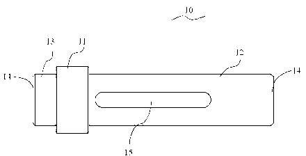
[0016] Participate figure 1 , Introduce a specific implementation of the bridge shaft 10 of the present invention. In this embodiment, the bridge shaft 10 includes a limiting portion 11, a first body portion 12, and a second body portion 13.

[0017] The first main body portion 12 extends from one end of the limiting portion 11, and the second main body portion 13 extends from the other end of the limiting portion 11 opposite to the first main body portion 12. In this embodiment, the cross-sectional area of ​​the limiting portion 11 is larger than the cross-sectional area of ​​the first main body portion 12 and th...


PUM


Abstract

The invention discloses a second motion shaft, comprising a limiting part, a first main body part and a second main body part, wherein the first main body part extends from one end of the limiting part, the second main body part extends from another end of the limiting part, and each of the first main body part and the second main body part is provided with a guide part. The guide parts are arranged on the first and second main body parts of the second motion shaft, so that when mounted, the second motion shaft can be positioned fast and exactly, and the mounting efficiency is improved.

Description

technical field [0001] The invention belongs to the technical field of machinery, and in particular relates to a bridge shaft. Background technique [0002] At present, common bearings can be divided according to the load direction they can bear: radial bearings, also known as centripetal bearings, which bear radial loads; thrust bearings, also known as thrust bearings, which take advantage of axial loads; radial thrust bearings Bearings, also known as centripetal thrust bearings, bear radial loads and axial loads at the same time. Although the radial thrust bearing can bear radial load and axial load at the same time, usually the installation of this kind of bearing is more complicated, it cannot be installed into the workpiece accurately and quickly, and the efficiency is low. Contents of the invention [0003] The purpose of the present invention is to provide a bridge shaft with high installation efficiency. [0004] In order to achieve the purpose of the above inven...

Claims


Application Information

Patent Timeline
IPC IPC(8): F16C3/02
Inventor 钱文明
Owner WUXI BAISHUN MACHINERY PLANT
Why Eureka
Try Eureka