Emergent button

A button and emergency technology, applied in mechanical control devices, instruments, control/adjustment systems, etc., can solve the problems of increasing the danger of pedestrians, unable to locate emergency buttons quickly and accurately, and achieve the effect of rapid and accurate positioning

Active Publication Date: 2017-12-05
KONE CORP
View PDF13 Cites 0 Cited by
  • Summary
  • Abstract
  • Description
  • Claims
  • Application Information

AI Technical Summary

Problems solved by technology

Since the position of the emergency button is difficult to attract the attention of pedestrians, there is also the risk that the emergency button cannot be located quickly and accurately in emergency situat

Method used


Image

  • Emergent button
  • Emergent button
  • Emergent button

Examples


Example Embodiment

[0037] The following is attached Figure 1 to 5 , Specifically describe the implementation of the present disclosure. The following embodiments take the moving walk as an example. Of course, the present disclosure is also applicable to escalators.

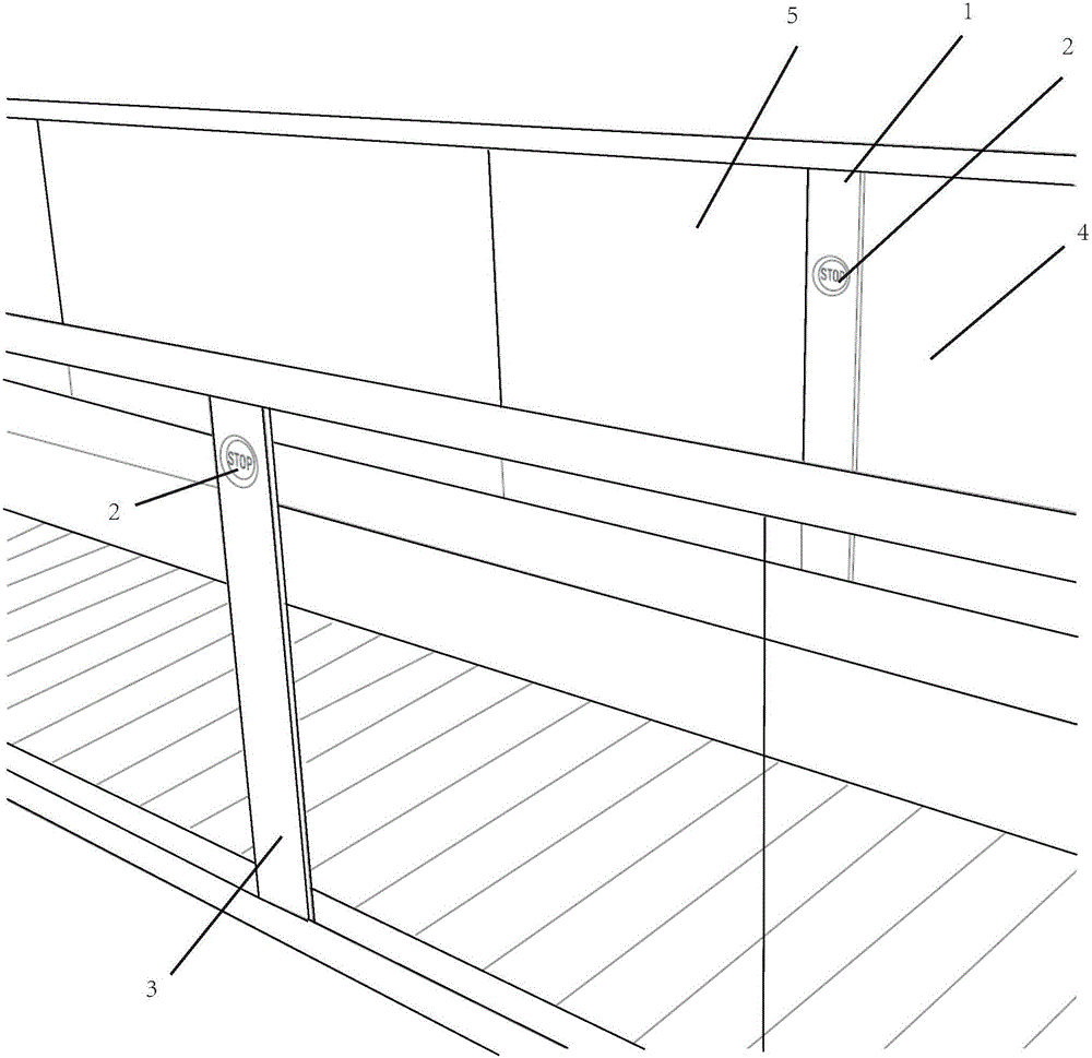
[0038] Such as figure 1 As shown, according to the first embodiment of the present disclosure, an emergency button 1 for escalators or moving walks is provided.

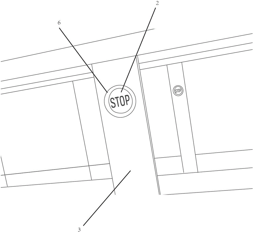
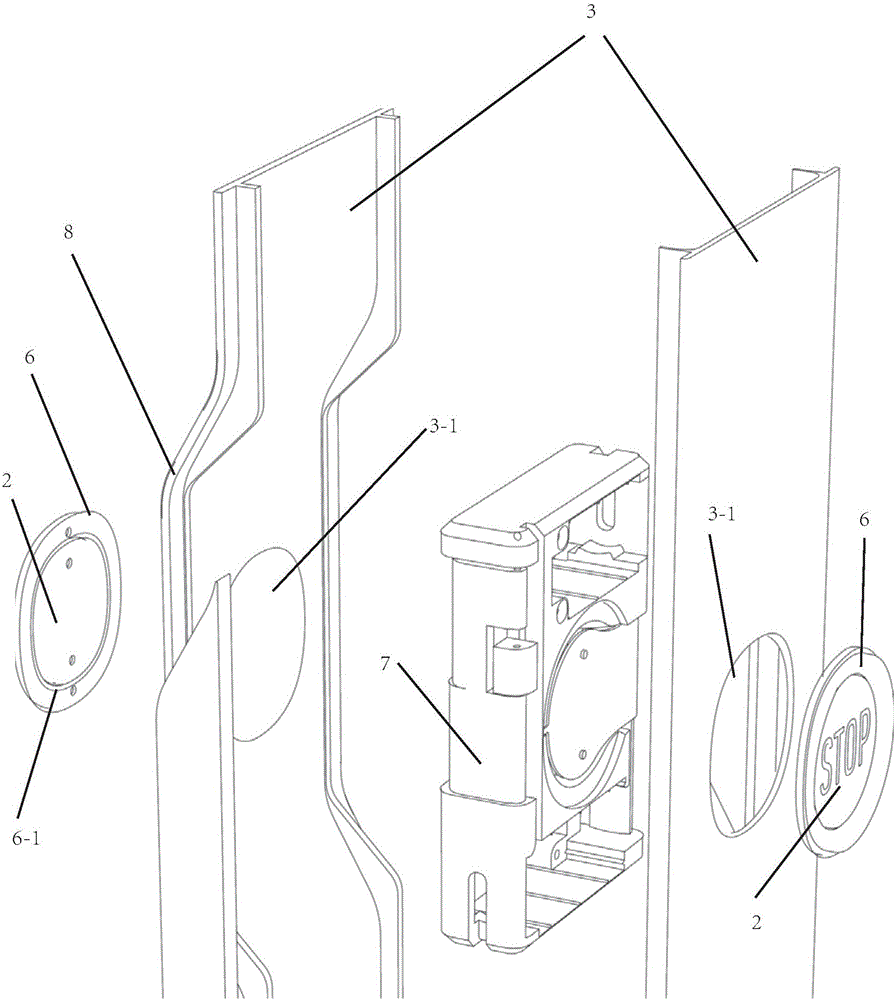
[0039] The emergency button 1 includes a button body 2 and a mounting strip 3.

[0040] The button body 2 is installed in the strip opening 3-1 of the installation strip 3 (see image 3 )in.

[0041] The installation slat 3 is embedded and installed between two adjacent side plates 4 and 5 of the escalator or the moving sidewalk.

[0042] The mounting strip 3 and the button body 2 have different colors from the side plates 4 and 5. The side panel can be, for example, transparent glass, such as figure 1 , figure 2 , Figure 4 with Figure 5 As shown.

[0043] The position of the ...


PUM


Abstract

An emergent button is used for escalators or moving pavements. The emergent button comprises a button body and a mounting strip board; the button body is installed in a strip board opening hole in the mounting strip board; the mounting strip board is embedded between adjacent two side boards of the escalator or the moving pavement; the mounting strip board and the button body are different from the side boards in color.

Description

technical field [0001] The present disclosure relates to an emergency button, in particular to an emergency button for an escalator or a moving walk. Background technique [0002] In the field of escalators or moving walks, when there is an abnormal operation, an emergency stop is required to ensure the safety of personnel. This emergency stop is usually achieved by a pedestrian or the relevant elevator operator pressing the emergency button. [0003] In the prior art, the emergency button is usually installed on the elevator cover plate at the entrance or exit of the escalator or moving walk. In order to allow pedestrians to quickly and accurately find the emergency button in an emergency, a reminder sign is usually provided near it. However, since the size of the emergency button is usually small and pedestrians are not familiar with the structure of the elevator, it is impossible to quickly and accurately locate the emergency button in emergency situations. [0004] In...

Claims


Application Information

Patent Timeline
IPC IPC(8): B66B29/00
CPCB66B29/00B66B23/00G05G1/02
Inventor 施逸民A.I.萨里V.劳塔
Owner KONE CORP
Why Eureka
Try Eureka