Auto-lift apparatus for CCTV camera maintenance

a technology for cctv cameras and lifts, applied in the direction of lifting equipment, color television, television systems, etc., can solve the problems of safety accidents, workmen having to rise and work on the structure, and breaking, so as to maintain the control stably on the ground

Active Publication Date: 2017-05-04
OTS
View PDF14 Cites 3 Cited by
  • Summary
  • Abstract
  • Description
  • Claims
  • Application Information

AI Technical Summary

Benefits of technology

[0014]According to the invention, a control unit which controls a CCTV camera to rise or fall is detachable from a case in a slot type, the control unit can be maintained on the ground by detecting the control unit from the case, or the control unit is provided such that a hand of a worker can reach the inside of a signal control box formed at a predetermined height of the structure, thereby stably maintaining the control on the ground, as an advantage.
[0015]In addition, according to the invention, a short circuit or the like caused by twist of the insulating band at the time of rising and falling of the CCTV camera unit can be prevented through the insulating band provided with twist preventing edges on both ends in a longitudinal direction o...

Problems solved by technology

CCTV cameras are used to grasp unmanned monitoring activities or road traffic conditions, the CCTV camera is installed at the upper portion of an indoor or outdoor structure to secure visibility of the camera, and there is difficulty that a worker has to rise and work on the structure using a ladder or a high place working vehicle to maintain the CCTV camera.
However, the band 6 is made of metal to enhance the strength, the metallic band has a limit to have a predetermined or more thickness to secure flexibility for being wound on the rotation reel 2, breaking may occur thereby during working for maintenance, and a safety accident may occur due to electricity flowing through the band at the time of electric leakage or short circuit.
In addition, the metallic band may be twisted during rising or falling to cause erroneous contact between terminals, thereby being short-circuited, which is a problem.
The CCTV camera includes a plurality of terminals such as a power supply terminal, image information transmission and reception terminals of the CCTV camera and/or drive signal transmission and ...

Method used


Image

  • Auto-lift apparatus for CCTV camera maintenance
  • Auto-lift apparatus for CCTV camera maintenance
  • Auto-lift apparatus for CCTV camera maintenance

Examples


Embodiment Construction

[0053]Hereinafter, preferred embodiments of the invention will be descried in more detail with reference to the accompanying drawings.

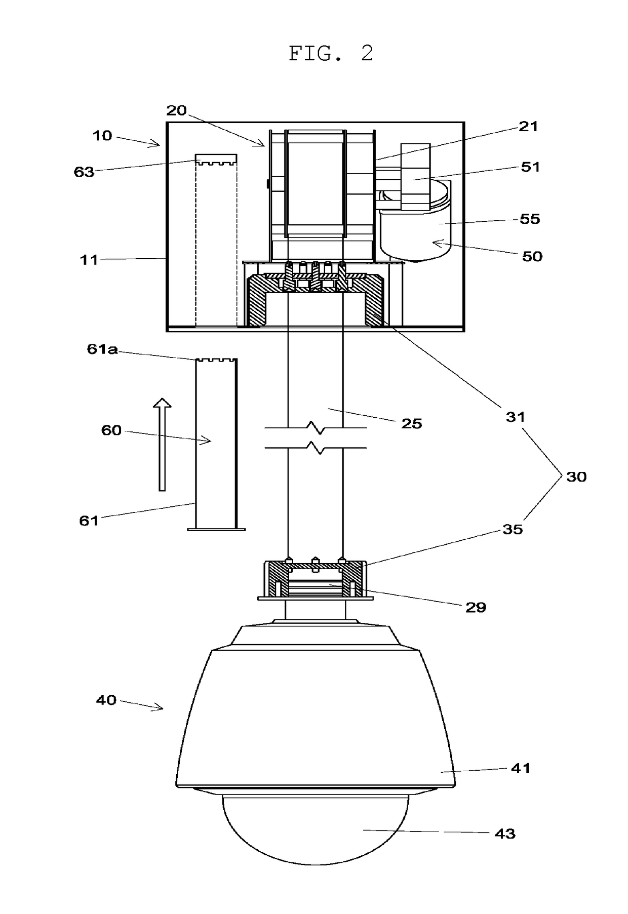
[0054]FIG. 2 is a front view illustrating an auto-lift apparatus for CCTV camera maintenance according to the invention. Referring to FIG. 2, the invention includes a case unit 10 which is fixed to an upper portion of an indoor or outdoor structure, a rising and falling unit 20 which is rotatably provided in the case unit 10, a terminal unit 30 which includes an upper socket 31 provided on a bottom face of the case unit 10 and an upper socket 35 fixed to an end portion of an insulating band 25 of the rising and falling unit 20, a CCTV camera unit 40 which is fixed to the lower socket 35, a drive unit 50 which is coupled to a rotation shaft of a winding reel 21 of the rising and falling unit 20, and a control unit 60 which controls the CCTV camera unit 40 to rise or fall through a drive command signal for the rising and falling unit 20, controls the CC...


PUM


Abstract

The present invention relates to an auto-lift apparatus for CCTV camera maintenance, wherein a CCTV camera is fixed to a lower end portion of a band wound with a predetermined width to maintain the CCTV camera on the ground, the band is made of an insulating material, a control unit which controls the CCTV camera to rise or fall is provided in a slot type, and the CCTV camera rises, falls, and is kept stopping through coupling of worm gears.

Description

TECHNICAL FIELD[0001]The present invention relates to an auto lift apparatus CCTV camera maintenance and, more specifically, to an auto lift apparatus for CCTV camera maintenance, in which the CCTV camera is fixed to a lower end portion of a band wound with a predetermined width to maintain the CCTV camera on the ground, the band is made of an insulating material to prevent electric leakage or short circuit even in case of rain, a control unit which controls the CCTV camera to rise or fall is detachable in a slot type or is provided at a predetermined height at which a hand of a worker can reach a ground structure, the CCTV camera rises, falls, and is kept stopping through coupling of worm gears, and monitoring can continue through an auxiliary camera during maintenance of a CCTV.BACKGROUND ART[0002]CCTV cameras are used to grasp unmanned monitoring activities or road traffic conditions, the CCTV camera is installed at the upper portion of an indoor or outdoor structure to secure vi...

Claims


Application Information

Patent Timeline
IPC IPC(8): H04N5/225H04N7/18B66D1/12
CPCH04N5/2253H04N7/183B66D1/12H04N23/50H04N23/54
Inventor SONG, MOO SANG
Owner OTS
Why Eureka
Try Eureka