
Fastener System

a fastener and system technology, applied in the field of fastener systems, can solve the problems of insufficient driving force to adequately drive the fastener through the working surface, the risk of overdriving the fastener, etc., and achieve the effects of reducing or even eliminating the drawbacks encountered, reducing the sound level of the system, and ensuring the safety of the fastener

Inactive Publication Date: 2017-05-11
BLUE POINT FASTENERS
View PDF9 Cites 0 Cited by
  • Summary
  • Abstract
  • Description
  • Claims
  • Application Information

AI Technical Summary

Benefits of technology

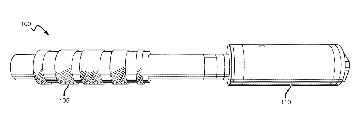
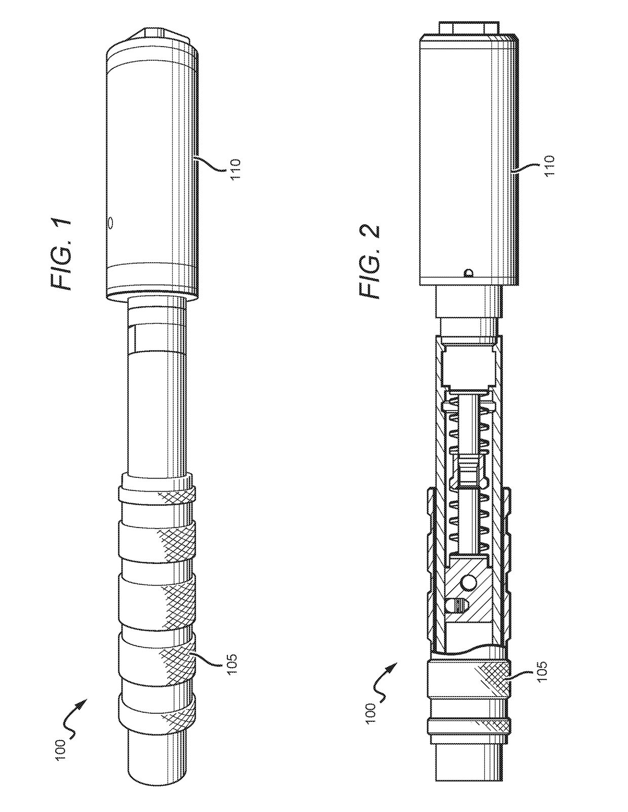
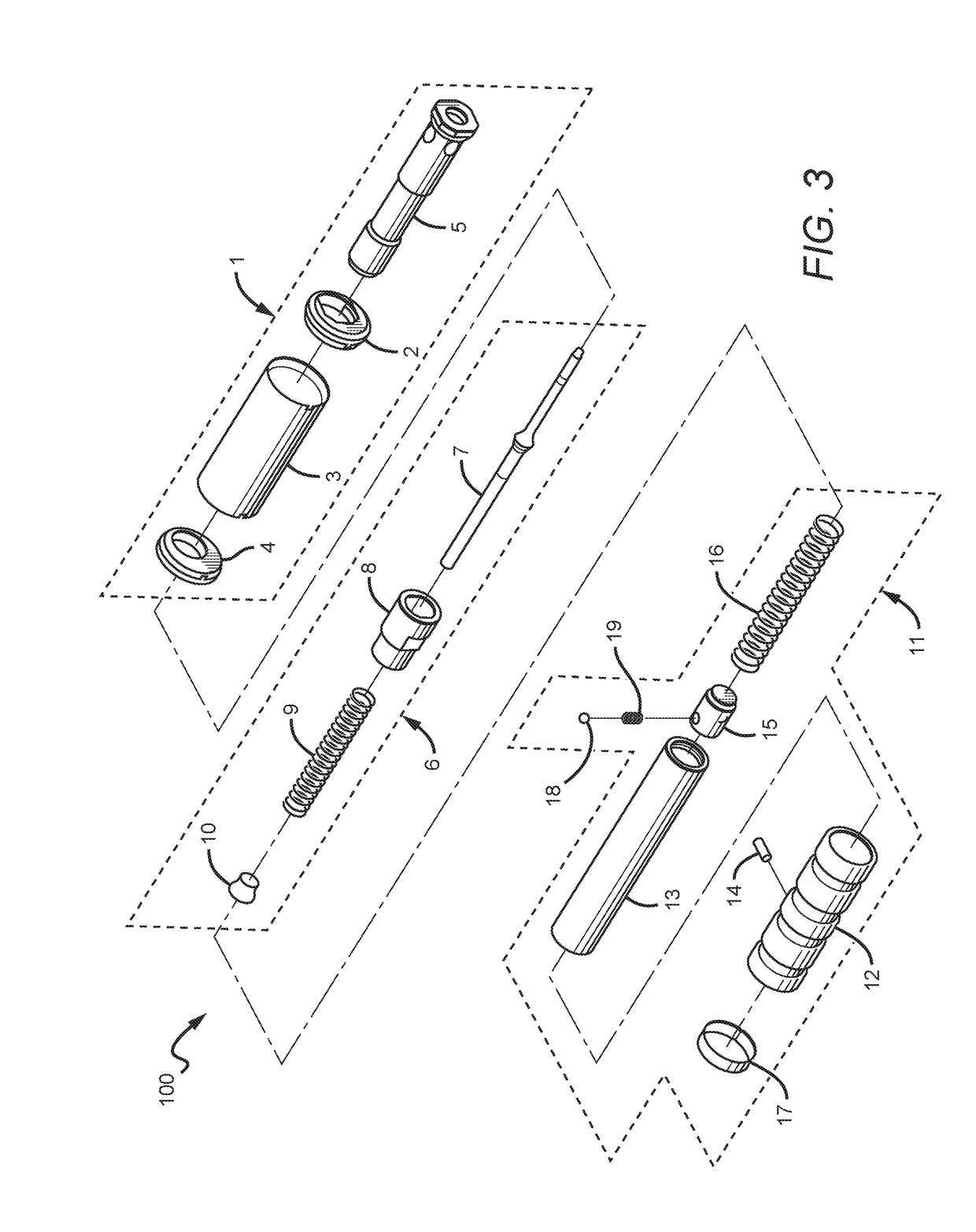
The inventive subject matter describes a fastener system that improves performance and reduces failures and spalling. The system includes a tool that drives the fastener into a work surface, with a longitudinal bore that guides the fastener and reduces sound levels. The system also includes a washer that uncouples from the tool as the fastener is driven out, and a tool that reduces the volume of sound and prevents overdriving the fastener through the work surface. Overall, the system provides stability, guidance, and optimal penetration of the fastener for better performance.

Problems solved by technology

On the one hand, if the first vent and the second vent are separated by too far of a distance then there may not be enough driving force to adequately drive the fastener through the working surface.
On the other hand, if the first vent and the second vent are too close to each other then there may be a risk of overdriving the fastener.

Method used


Image

  • Fastener System
  • Fastener System
  • Fastener System

Examples


Embodiment Construction

[0040]The following discussion provides example embodiments of the inventive subject matter. Although each embodiment represents a single combination of inventive elements, the inventive subject matter is considered to include all possible combinations of the disclosed elements. Thus if one embodiment comprises elements A, B, and C, and a second embodiment comprises elements B and D, then the inventive subject matter is also considered to include other remaining combinations of A, B, C, or D, even if not explicitly disclosed.

[0041]As used in the description herein and throughout the claims that follow, the meaning of “a,”“an,” and “the” includes plural reference unless the context clearly dictates otherwise. Also, as used in the description herein, the meaning of “in” includes “in” and “on” unless the context clearly dictates otherwise.

[0042]Also, as used herein, and unless the context dictates otherwise, the term “coupled to” is intended to include both direct coupling (in which tw...


PUM


Abstract

A fastener system comprising a tool and fastener is contemplated. The tool comprises an elongated member having a longitudinal bore that receives the fastener. The fastener is driven by the tool into a working surface whereby first and second vents capture a portion of the propellant gas to optimize penetration of the fastener and reduce the sound level. The fastener typically has a first diameter and a second diameter that meet at a step. A washer can receive the first diameter of the fastener. It is contemplated that the alignment of the fastener as it penetrates the work surface is maintained by at least one of (i) the head of the fastener and the longitudinal bore, (ii) washer, and (iii) a clip to reduce failures and spalling.

Description

[0001]This application claims the benefit of priority to U.S. Provisional Application Ser. No. 62 / 189,047 filed on Jul. 6, 2015. All extrinsic materials identified herein are incorporated by reference in their entirety.FIELD OF THE INVENTION[0002]The field of the invention is fastener systems and more particularly explosively driven fastener systems.BACKGROUND[0003]The background description includes information that may be useful in understanding the present invention. It is not an admission that any of the information provided herein is prior art or relevant to the presently claimed invention, or that any publication specifically or implicitly referenced is prior art.[0004]These and all other extrinsic materials discussed herein are incorporated by reference in their entirety. Where a definition or use of a term in an incorporated reference is inconsistent or contrary to the definition of that term provided herein, the definition of that term provided herein applies and the defini...

Claims


Application Information

Patent Timeline
IPC IPC(8): B25C1/18B25C1/12
CPCB25C1/12B25C1/18B25C1/188
Inventor ARMSTRONG, WILLIAM D.
Owner BLUE POINT FASTENERS
Learn More