Building frame connector and method of use

Inactive Publication Date: 2017-05-11
CARBON DEV SERVICES LLC
View PDF31 Cites 12 Cited by
  • Summary
  • Abstract
  • Description
  • Claims
  • Application Information

AI Technical Summary

Benefits of technology

[0008]It is contemplated that one or two version of the present building frame connector may be used in a single structure and throughout the project. This would realize efficiencies in fabrication due to standardization of connectors and reduce errors in the erection of members. However, it is also contemplated that more than two versions of the present building frame connector may be implemented on the project based upon loading requirements. Efficiencies in this manner could be obtained by having a pre-d

Problems solved by technology

As an architect with a background in structural engineering, the inventor became frustrated with the current building methods and their inefficiencie

Method used


Image

  • Building frame connector and method of use
  • Building frame connector and method of use
  • Building frame connector and method of use

Examples


Embodiment Construction

[0017]The following detailed description of the present invention references the accompanying drawing figures that illustrate specific embodiments in which the invention can be practiced. The embodiments are intended to describe aspects of the present invention in sufficient detail to enable those skilled in the art to practice the invention. Other embodiments can be utilized and changes can be made without departing from the spirit and scope of the present invention. The present invention is defined by the appended claims and, therefore, the description is not to be taken in a limiting sense and shall not limit the scope of equivalents to which such claims are entitled.

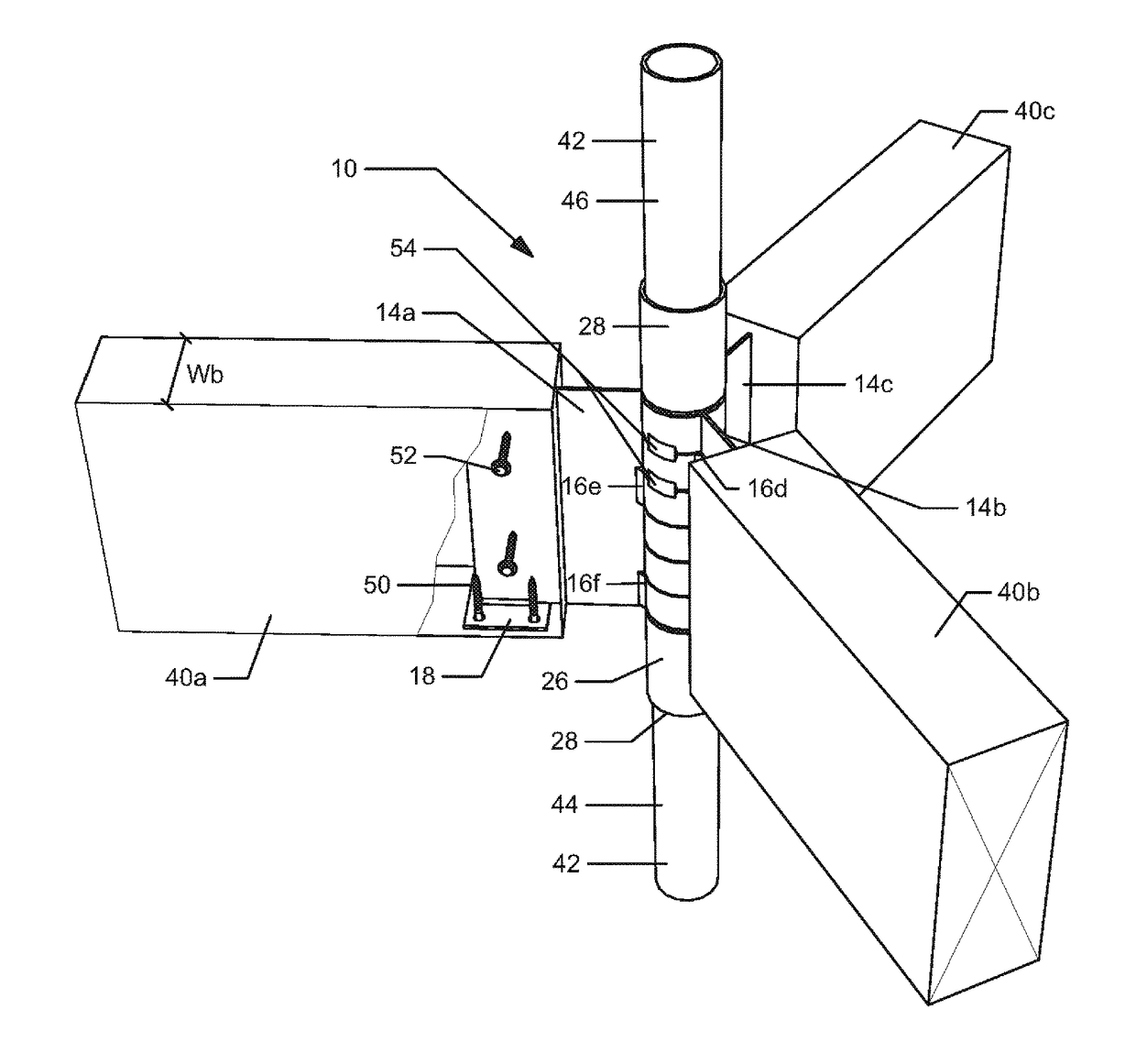
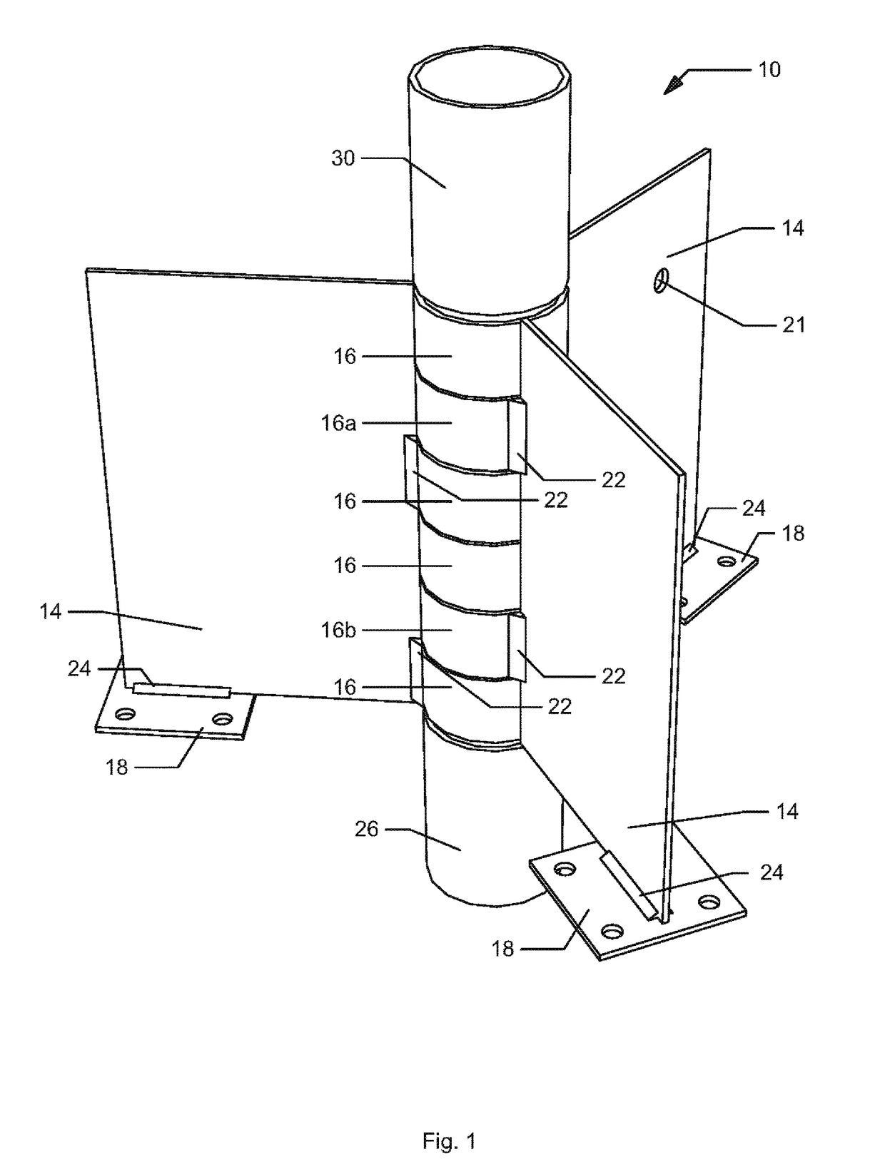
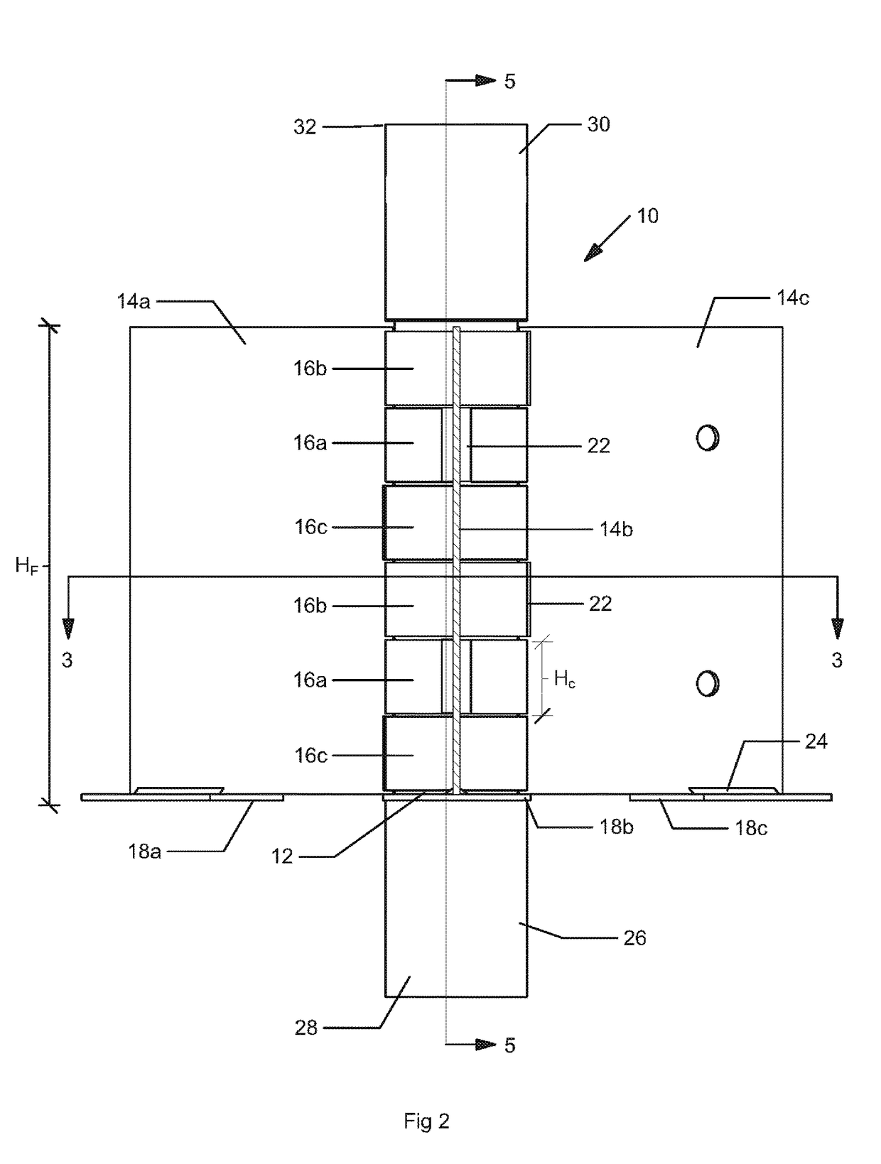
[0018]The present invention is directed toward a building frame connector 10 which is a structural node used in building construction that joins multiple beams to a steel column and allows for on-site vertical and angular orientation adjustment. Turning to FIG. 1, building frame connector 10 includes a pin member 12 ...


PUM


Abstract

A building frame connector for connecting beams to columns to create a building frame. The building frame connector includes a pin member and plurality of fins mounted on said pin member for rotation relative to said pin. The pin may be in alignment with the column, and the fins allow connection of the beams to the columns The fins may be disposed to rotate relative to said pin member about a longitudinal axis of the pin. In one embodiment the pin member may have an outer diameter and the fins have a collar with an inner diameter is greater than said outer diameter of said pin allowing for the collars to rotate about the pin member. The present building frame connector may also include at least one coupling member coupled to the pin member, wherein the coupling member facilitates the connection of the building frame connector to a building column.

Description

CROSS REFERENCE TO RELATED APPLICATIONS[0001]This application claims the benefit of U.S. Provisional Patent Application No. 62 / 251,211 filed Nov. 5, 2015, the entire disclosure of which is hereby incorporated by reference.BACKGROUND OF THE INVENTION[0002]As an architect with a background in structural engineering, the inventor became frustrated with the current building methods and their inefficiencies. In typical conventional wood frame construction, load bearing stick-framed walls are crafted on site by skilled craftsmen and provide the structural skeleton of each building. In certain markets, there is an increased demand for these skilled carpenters, which is driving up costs of construction and stalling out projects. Moving to a non-load bearing wall design with post and beam construction speeds up the construction time and allows for increased use of less skilled labor.[0003]Typical construction methods often use “hinged” connections as these connections are the easiest and che...

Claims


Application Information

Patent Timeline
IPC IPC(8): E04B1/19E04B1/41
CPCE04B1/1909E04B2001/1957E04B2001/1918E04B1/40E04B1/2608E04B2001/2616E04B2001/2648E04B2001/2676
Inventor HIGGINS, BRIAN
Owner CARBON DEV SERVICES LLC
Why Eureka
Try Eureka