
Lighting device

a technology of lighting device and light source, which is applied in the direction of light and heating apparatus, semiconductor devices for light sources, refractors, etc., can solve the problems of inconvenient control of lighting device by a user, and achieve the effect of minimizing interference, minimizing signal loss, and improving convenience of a user of lighting devi

Inactive Publication Date: 2017-05-11
LG INNOTEK CO LTD
View PDF0 Cites 14 Cited by
  • Summary
  • Abstract
  • Description
  • Claims
  • Application Information

AI Technical Summary

Benefits of technology

The present invention provides a lighting device that can be controlled wirelessly, making it more convenient for users. The device has a structure that allows for quick signal transmission between components, reducing signal loss. Additionally, the invention separates and insulates the ground pattern of a communication element from the ground pattern of a power supply element, minimizing interference between the two functions. The lower substrate has pads with holes, while the terminals on the upper substrate fit into the holes, making connection members unnecessary.

Problems solved by technology

Therefore, it is inconvenient for a user of a lighting device to control the lighting device.

Method used


Image

  • Lighting device
  • Lighting device
  • Lighting device

Examples


Embodiment Construction

[0034]The embodiments of the present invention will be described with reference to the accompanying drawings in such a manner that the embodiments may be easily carried out by those skilled in the art to which the present invention pertains. However, the present invention may be implemented in various forms and is not limited to the embodiments.

[0035]It will also be understood that the terms “comprises”, “includes”, and “has”, when used herein, specify the presence of stated elements, but do not preclude the presence or addition of other elements, unless otherwise defined.

[0036]For clarity of description, parts having no relation to description are omitted. Thicknesses of layers and regions are exaggerated for clarity. Like reference numerals are assigned to like elements throughout the present disclosure and the drawings.

[0037]It will be understood that when a layer, film, region, or plate is referred to as being “formed on” another layer, film, region, or plate, it can be directly...


PUM

PropertyMeasurementUnit
poweraaaaaaaaaa
driving poweraaaaaaaaaa
brightnessaaaaaaaaaa

Abstract

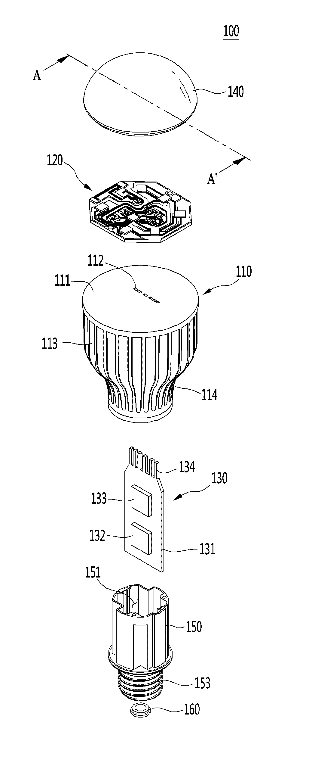
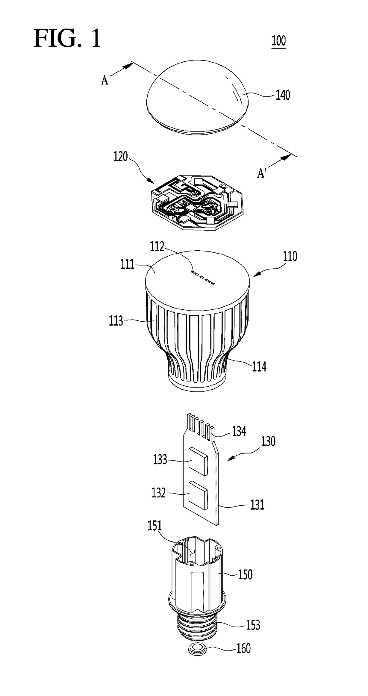
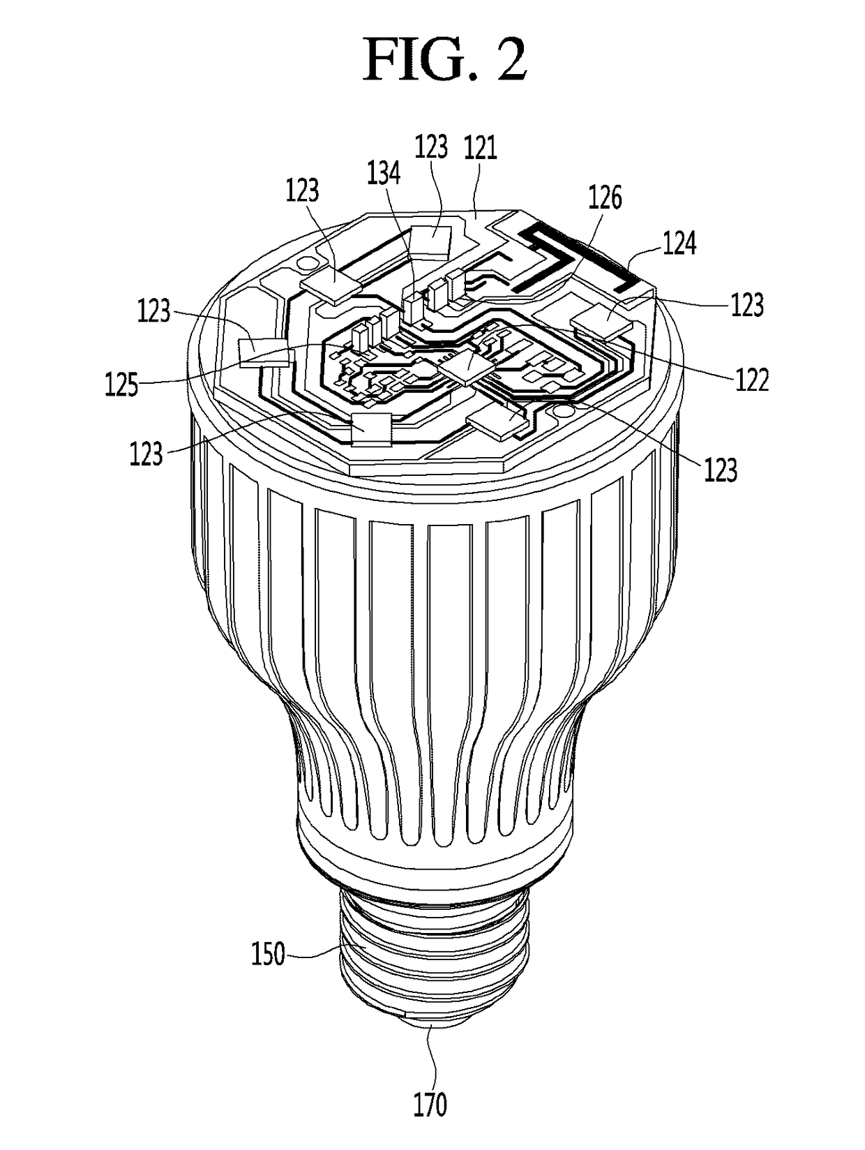
A lighting device according to an embodiment of the present invention comprises: a heat dissipating frame having a receiving recess formed therein and a plurality of insertion holes formed in the upper surface thereof; a light source module mounted on an upper surface of the heat dissipating frame, and including a first substrate in which a plurality of coupling holes is formed at positions facing the plurality of insertion holes; and a control module received in the receiving recess of the heat dissipating frame, and including a second substrate having a plurality of connecting terminals formed on a side surface thereof and projecting in a lengthwise direction, wherein the control module is disposed vertically upright within the receiving recess such that the plurality of connecting terminals faces upward, and the plurality of connecting terminals is inserted in the plurality of insertion holes and the plurality of coupling holes is connected to the light source module.

Description

TECHNICAL FIELD[0001]Embodiments relate to a lighting device having a wireless communication function.BACKGROUND ART[0002]Generally, lighting devices are provided in various forms, e.g., a ceiling-direct-attached lamp, a landscape lighting lamp, a night lamp, a desk lamp, etc., according to purposes thereof. These lighting devices need to be turned on with sufficient brightness levels according to the purposes thereof. Thus, recent lighting devices use light emitting diodes (LEDs). The LEDs have advantages such as low power consumption, a semi-permanent lifespan, a fast response time, high stability, and environmental friendliness, as compared with the existing light sources, e.g., fluorescent lamps and incandescent lamps. In this regard, research has been conducted to replace LEDs used as the existing light source.[0003]However, such a lighting device is turned on or off by a switch connected via a wire. Therefore, it is inconvenient for a user of a lighting device to control the l...

Claims


Application Information

Patent Timeline
Patent Type & Authority Applications(United States)
IPC IPC(8): F21K9/238H05B33/08F21V3/02F21V5/04F21V29/77F21K9/237F21K9/64F21V9/16H05B37/02F21K9/232H05B44/00
CPCF21K9/238H05B37/0272H05B33/0845F21V3/02F21K9/232F21Y2115/10F21K9/237H05B33/0809F21K9/64F21V9/16F21V5/04F21V29/77F21V23/006F21V3/049F21V3/0625F21V9/30H05B45/20H05B47/19Y02B20/30H05B45/37H05B45/30H05B45/10
Inventor CHO, SHINKIM, JUNG TAE
Owner LG INNOTEK CO LTD
Learn More