Polarizer and transparent display

a transparent display and polarizer technology, applied in the field of transparent display technology, can solve the problems of serious severely affecting the brightness and image quality of the background object, and the operation of the lower polarizer cannot be completely achieved. , to achieve the effect of increasing the transmittance of light, reducing the loss of light reflected by the background object in the transparent region, and reducing the loss of ligh

Active Publication Date: 2017-05-11
WUHAN CHINA STAR OPTOELECTRONICS TECH CO LTD
View PDF1 Cites 10 Cited by
  • Summary
  • Abstract
  • Description
  • Claims
  • Application Information

AI Technical Summary

Benefits of technology

[0022]The polarizer comprises the polarization regions and the transmittance regions at the same time, and the polarization regions are employed to transmit through linear polarization light of the specific direction, and the transmittance regions are employed to transmit through natural light. Therefore, the polarizer can selectively and partially transmits the natural light to be applied for the display of various requirements. The transmittance regions of the polarizer do not filter light. Thus, the display utilizing the polarizer can have higher transmittance and the application is more flexible.
[0023]In the transparent display of the present invention, the vertical projections of the plurality of first polarization regions of the first polarizer on the liquid crystal layer completely cover the plurality of display regions correspondingly one to one, and the vertical projections of the plurality of second polarization regions of the second polarizer on the liquid crystal layer completely cover the plurality of display regions correspondingly one to one. Namely, the vertical projections of the plurality of first transmittance regions of the first polarizer on the liquid crystal layer fall in the plurality of transparent regions correspondingly one to one, and the vertical projections of the plurality of second transmittance regions the second polarizer on the liquid crystal layer fall in the plurality of transparent regions correspondingly one to one. Therefore, the first polarizer and the second polarizer do not absorb the light entering or outgoing the positions of the transparent regions of the liquid crystal layer. It tremendously raises the transmittance of the light at the transparent display positions of the transparent display, and promotes the brightness and the image quality of the background object pictures shown by the transparent display.

Problems solved by technology

Meanwhile, the light passing through the lower polarizer cannot completely accomplish the operation of rotating 90° polarization state.
The transmittance of the light reflected by the background object in the transparent regions is seriously lost to severely influence the brightness and the image quality of the background object.

Method used


Image

  • Polarizer and transparent display
  • Polarizer and transparent display
  • Polarizer and transparent display

Examples


Embodiment Construction

[0028]For better explaining the technical solution and the effect of the present invention, the present invention will be further described in detail with the accompanying drawings in the specific embodiments.

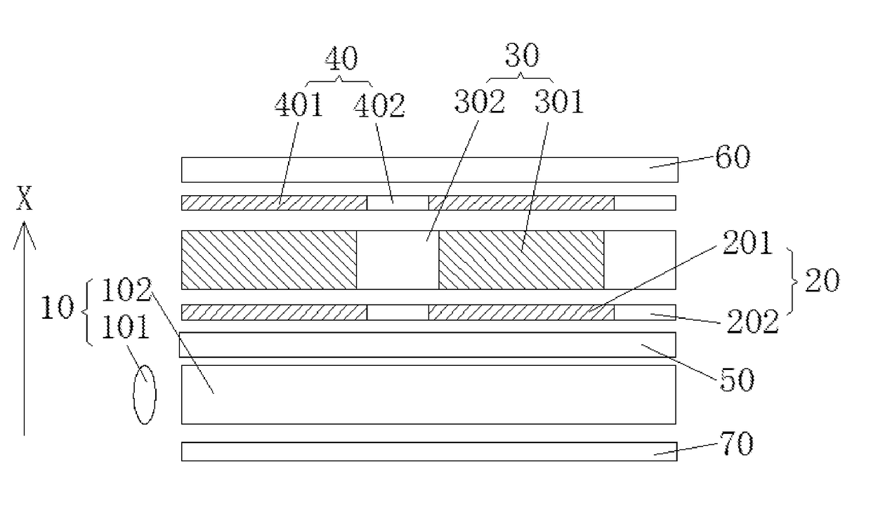
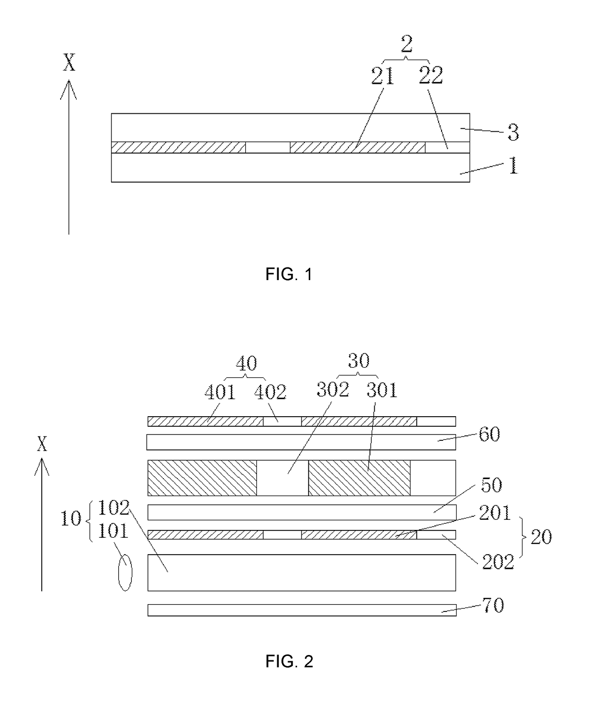
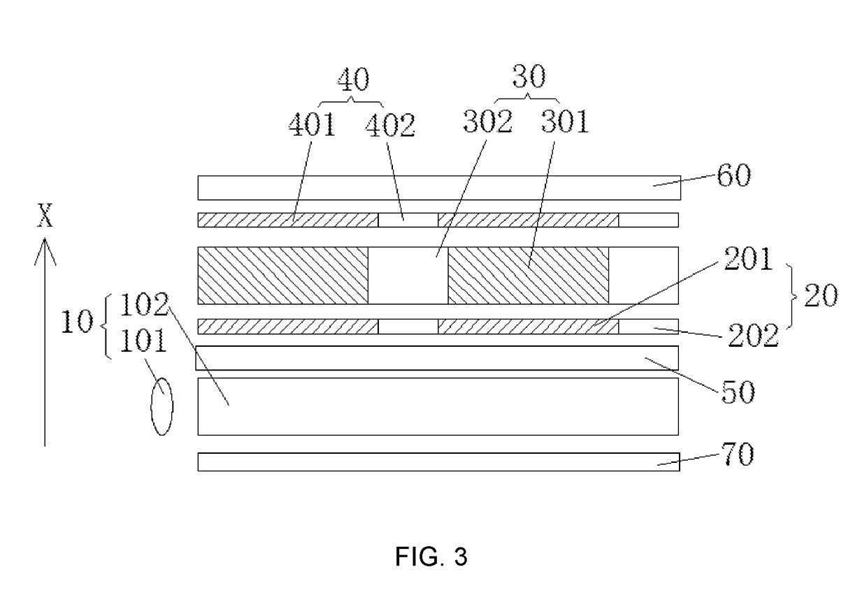
[0029]Please refer to FIG. 1. The embodiment of the present invention provides a polarizer. The X direction shown in FIG. 1 is defined to be the first direction X. The polarizer comprising a first protective layer 1, a polarization layer 2 and a second protective layer 3, which are sequentially stacked up in the first direction X, and the polarization layer 2 comprises a plurality of polarization regions 21 and a plurality of transmittance regions 22, and the plurality of polarization regions 21 and the plurality of transmittance regions 22 are alternately aligned on a plane perpendicular to the first direction X, and the polarization regions 21 are employed to transmit through linear polarization light in a polarization axis of the polarization regions 21, and the transmittanc...


PUM

PropertyMeasurementUnit
transmittanceaaaaaaaaaa
transparentaaaaaaaaaa
areaaaaaaaaaaa

Abstract

The present invention discloses a polarizer, comprising a first protective layer, a polarization layer and a second protective layer, which are sequentially stacked up in a first direction, and the polarization layer comprises a plurality of polarization regions and a plurality of transmittance regions, and the plurality of polarization regions and the plurality of transmittance regions are alternately aligned on a plane perpendicular to the first direction, and the polarization regions are employed to transmit through linear polarization light in a polarization axis of the polarization regions, and the transmittance regions are employed to transmit through natural light. The polarizer of the present invention can selectively transmit the natural light to raise the transmittance of the display utilizing the polarizer. The present invention also discloses a transparent display with high transmittance.

Description

FIELD OF THE INVENTION[0001]The present invention relates to a transparent display technology field, and more particularly to a polarizer and a transparent display.BACKGROUND OF THE INVENTION[0002]The transparent display means that the display itself possesses the light penetration of a certain degree, which can allow the user can clearly see the background behind the display as watching the display. Therefore, the transparent display is applied for building widows, car windows or shop windows.[0003]For realizing to show the image pictures and the background pictures at the same time, the transparent display generally divides the pixel regions in the panel into the display regions and the transparent regions. The display regions show the image pictures, and the transparent regions do not comprise color resist to achieve the transparent display. Although the transparent regions do not have color resist, the light reflected by a portion of the background object is absorbed by the lowe...

Claims


Application Information

Patent Timeline
Patent Type & Authority Applications(United States)
IPC IPC(8): G02F1/1335F21V8/00
CPCG02F1/133528G02B6/0055G02F2001/133567G02F2001/133538G02F2001/133562G02B6/0056G02B5/3033G02B5/3058G02F1/133538G02F1/133562G02F1/133567
Inventor TANG, YUEJUN
Owner WUHAN CHINA STAR OPTOELECTRONICS TECH CO LTD
Why Eureka
Try Eureka