Press sensor and electronic device

a technology of electronic devices and sensors, applied in the field of press sensors, can solve problems such as the inability to detect a signal from the plla

Active Publication Date: 2017-05-11
MURATA MFG CO LTD
View PDF6 Cites 10 Cited by
  • Summary
  • Abstract
  • Description
  • Claims
  • Application Information

AI Technical Summary

Benefits of technology

[0006]An object of the present invention is to provide a press sensor and an electronic device which can prevent produced charges from being cancelled irrespectively of a pressing position, and detect a press.

Problems solved by technology

As a result, there is a problem that it is not possible to detect a signal from the PLLA, and detect a pressing force with respect to the PLLA.

Method used


Image

  • Press sensor and electronic device
  • Press sensor and electronic device
  • Press sensor and electronic device

Examples


Embodiment Construction

[0027]An “electronic device” including a “press sensor” according to the present invention will be described by using a touch panel as an example.

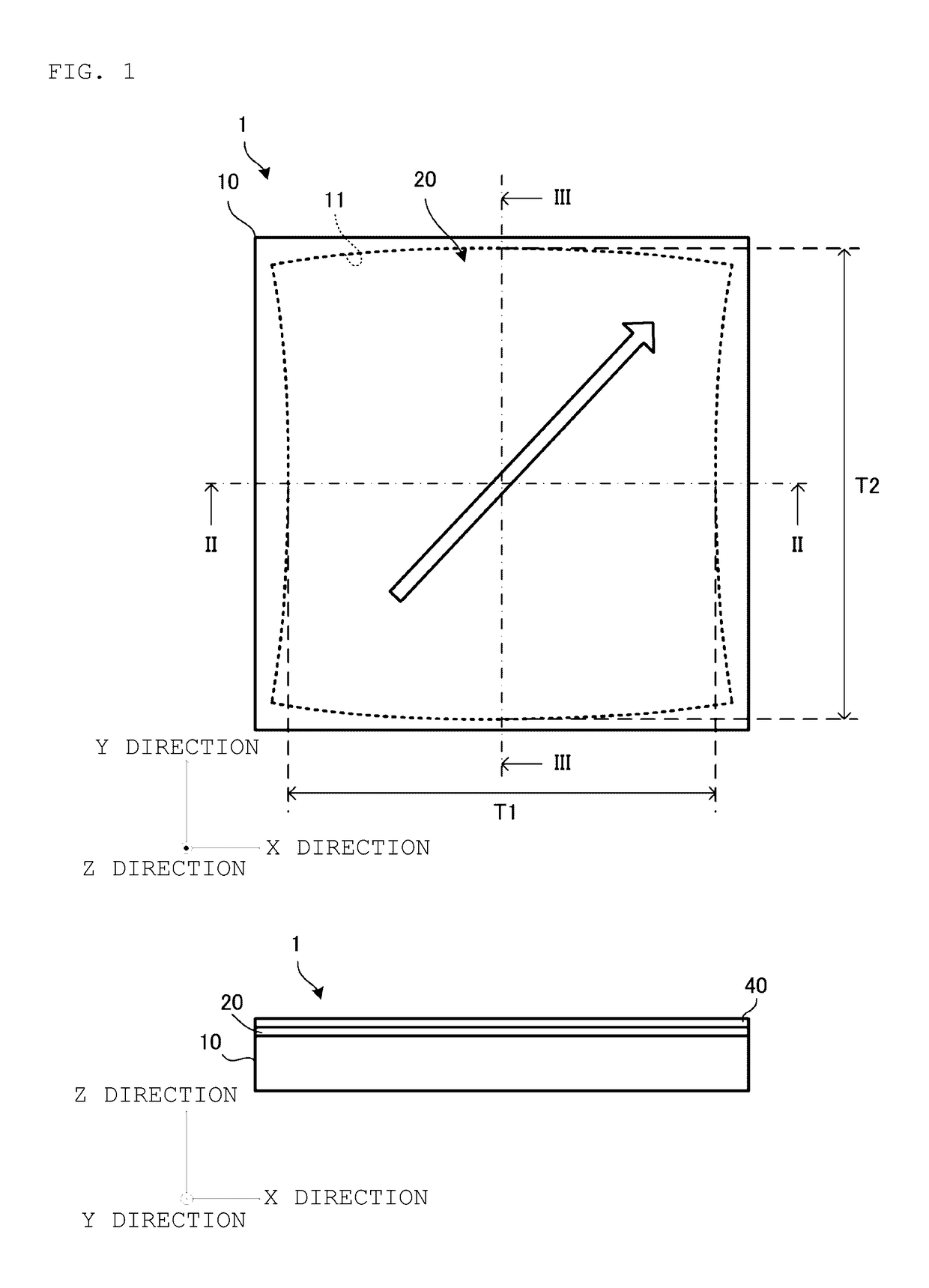
[0028]FIG. 1 is an external appearance plan view and a front view of the touch panel according to the present embodiment.

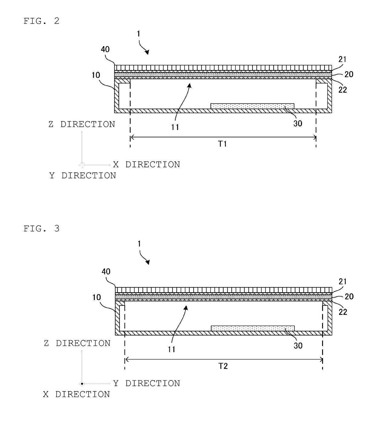
[0029]FIG. 2 is a sectional view taken along a line II-II in FIG. 1. FIG. 3 is a sectional view taken along a line III-III in FIG. 1.

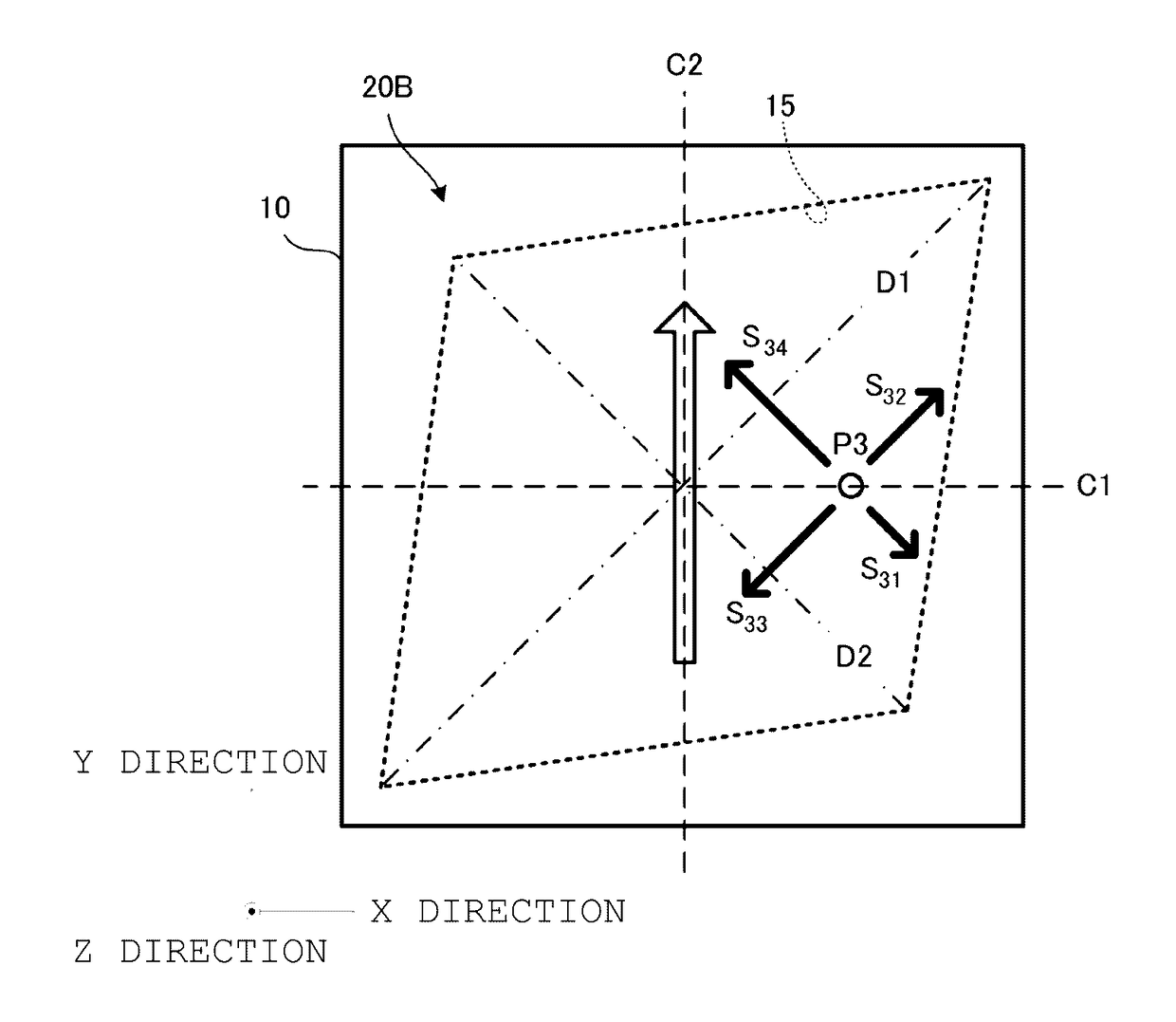
[0030]A touch panel 1 includes a housing 10 of a nearly cuboid shape. A width direction (lateral direction) of the housing 10 will be referred to as an X direction, a length direction (longitudinal direction) will be referred to as a Y direction and a thickness direction will be referred to as a Z direction. The present embodiment will be described assuming that the length of the housing 10 in the X direction and the length of the housing 10 in the Y direction are the same, i.e., the housing 10 has a square shape in a plan view. A surface of the square shape of the housing 10 will be referr...


PUM


Abstract

A touch panel that includes a housing defining an opening and a piezoelectric film covering the opening. The opening has a shape whose lengths in an X direction and a Y direction are different. The piezoelectric film is stretched in a uniaxial direction, and is aligned such that the uniaxial direction forms an angle of 45 degrees with respect to the X direction and the Y direction.

Description

CROSS REFERENCE TO RELATED APPLICATIONS[0001]The present application is a continuation of International application No. PCT / JP2015 / 073177, filed Aug. 19, 2015, which claims priority to Japanese Patent Application No. 2014-167534, filed Aug. 20, 2014, the entire contents of each of which are incorporated herein by reference.FIELD OF THE INVENTION[0002]The present invention relates to a press sensor which includes a piezoelectric film, and an electronic device.BACKGROUND OF THE INVENTION[0003]Patent Document 1 discloses a touch panel which detects a touch position and a push amount by using a piezoelectric film. Polylactic acid (PLLA) stretched in a uniaxial direction is used for the piezoelectric film of the touch panel disclosed in Patent Document 1. When this PLLA is pressed, the PLLA is distorted in a normal direction of a plane. This distortion applies a force of contracting or stretching the PLLA in a direction of 45 degrees with respect to a stretching direction, and produces n...

Claims


Application Information

Patent Timeline
Patent Type & Authority Applications(United States)
IPC IPC(8): G06F3/041
CPCG06F2203/04105G06F3/041G06F3/0414
Inventor ANDO, MASAMICHIMORI, KENICHI
Owner MURATA MFG CO LTD
Why Eureka
Try Eureka