
System and method for the operator control and for the monitoring of an automation system over the internet using an asymmetric internet connection

a technology of operator control and internet connection, applied in the field of system and method for transmitting data over the internet, can solve the problem that non-visible data processing devices cannot be directly addressed from outside the local network

Inactive Publication Date: 2007-04-26
SIEMENS AG
View PDF11 Cites 5 Cited by
  • Summary
  • Abstract
  • Description
  • Claims
  • Application Information

AI Technical Summary

Benefits of technology

[0010] transmitting information to the Internet server by the client for maintaining the first transmission channel, the information informing the Internet server that there is an intention to further transmit user data to the Internet server for avoiding cancellation of the first transmission channel by the Internet server;
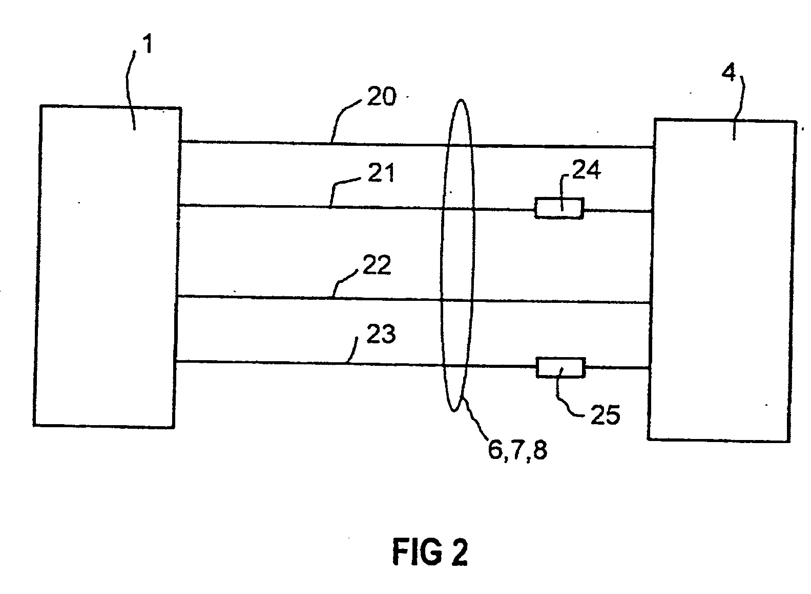
[0019] Specifically, two connection requests are successively transmitted to the Internet Server of the automation system from the client which can serve as a fully capable operator control and monitoring system after the bidirectional data connections have been set up. The Internet Server responds to these connection requests and thus makes available two asymmetrical data connections which are independent of one another and via which the client, as B&B system (Operating and Monitoring system) and the automation system can communicate with one another at their own initiation. A bidirectional data connection, which also permits data to be transmitted from the server to the client, is functionally safeguarded between the client and server, or in other words between the operator control and monitoring system and the automation system. This is based on the establishment of the two independent data connections to the server via the Internet which are set up from the client. By way of these two “dedicated lines”, the client is permanently connected to the server so that bidirectional transmission of data, independently in terms of timing, is made possible in both directions between the client and server. Such a data connection is suitable in particular for operating and monitoring an automation system, with the client being able to function as an operator control and monitoring system which can be activated from any computer which is connected to the Internet. In contrast to conventional Internet data connections, an asymmetrical data transmission method is thus obtained which does not require the client to be visible on the Internet or to have installed a web server (IIS=Internet Information Server). This makes it possible to set up a bidirectional data connection to a server at any desired location in the world, in front of and behind fire walls. Because the data connection is activated from the client, i.e. from the B&B system, it is not necessary for the server to actively set up a connection to the client at its own initiation. Furthermore, it is not necessary to change the configuration of the client.
[0021] A particularly preferred application of the present invention using existing Internet infrastructures for a bidirectional data transmission, is to provide the method for operating and monitoring an automation system is provided over the Internet. A connection of the automation and communications technology can be configured easily in such a way that the operator control and monitoring system of the client initiates the provision of the transmission channels as a distributed object, in particular as a DCOM object, and that the connection setup to the automation system is made via a DCOM server.

Problems solved by technology

Therefore, the non-visible data processing devices cannot be directly addressed from outside the local network as the devices communicate using the official IP address of the NAT-router.

Method used


Image

  • System and method for the operator control and for the monitoring of an automation system over the internet using an asymmetric internet connection
  • System and method for the operator control and for the monitoring of an automation system over the internet using an asymmetric internet connection
  • System and method for the operator control and for the monitoring of an automation system over the internet using an asymmetric internet connection

Examples


Embodiment Construction

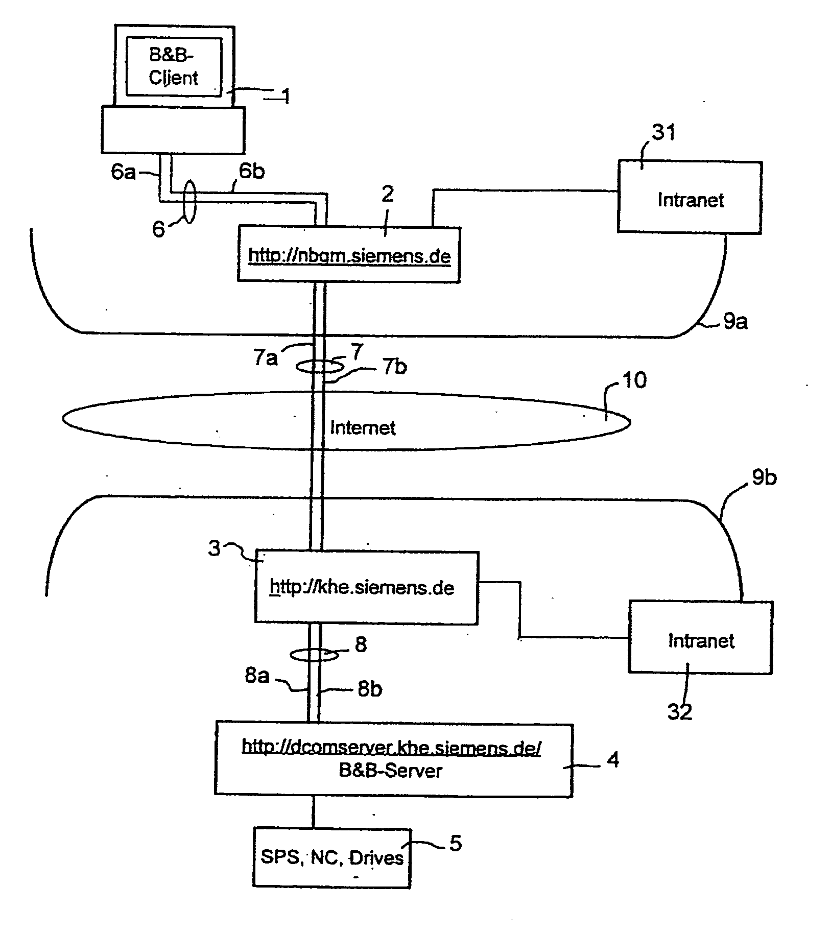
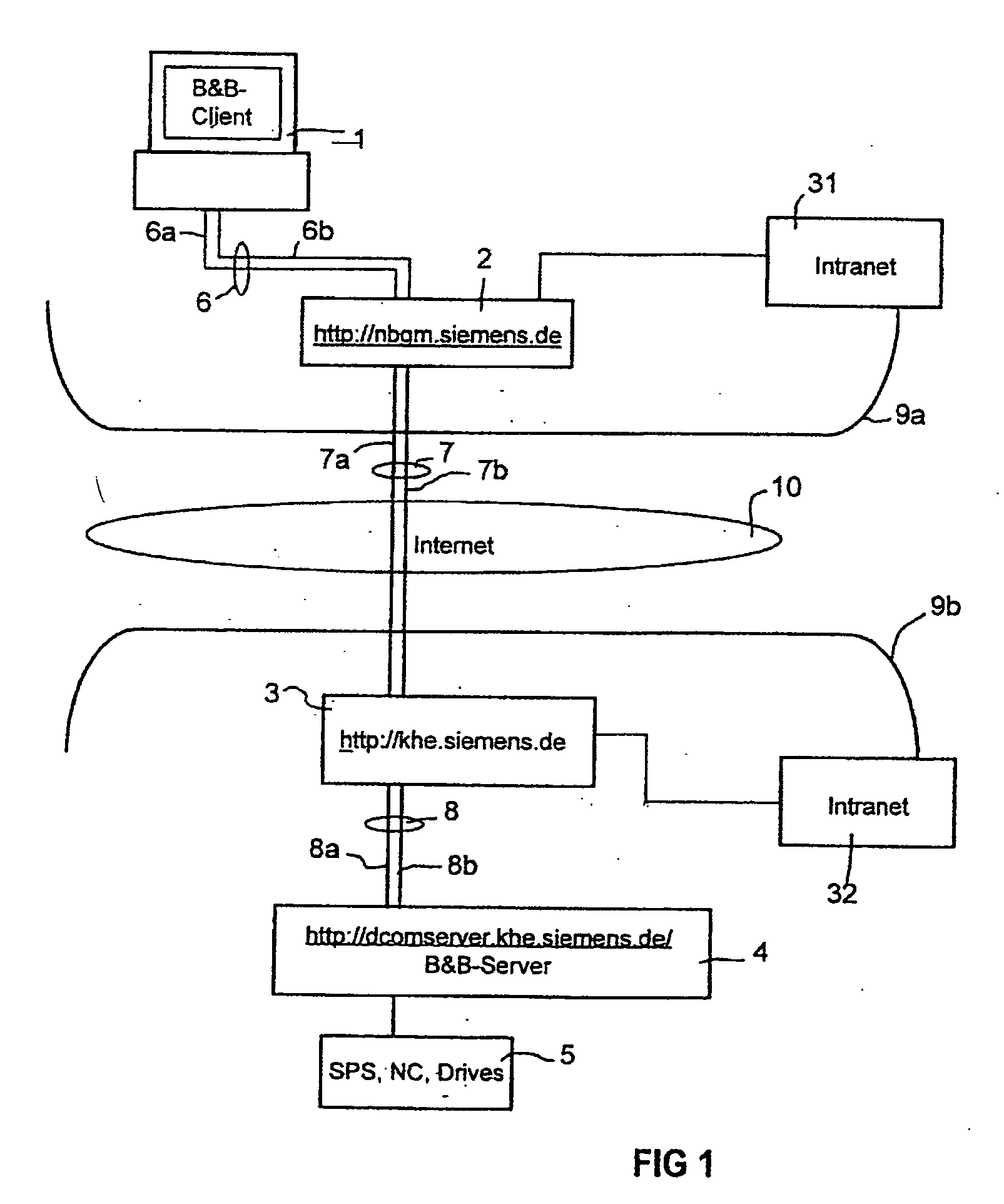
[0026]FIG. 1 shows an exemplary embodiment of a system for operating and monitoring automation systems 5 which have, for example, stored program controllers (SPS), numerical controllers (NC) and / or drives. The system has an operator control and monitoring system 1 (B&B client) which is connected to a fire wall computer 2 (=proxy) embodied as an NAT-router via an internal, local data network 6, for example a local Ethernet. The operator control and monitoring system 1, which is also referred to below for short as B&B system 1, is assigned a local Intranet address (=IP address only valid in a local network) which is not known on the Internet. Therefore, the B&B system 1 is not visible on the internet. The fire wall of the fire wall computer 2 which surrounds the internal communications network 31 (=Intranet 31) of the fire wall server 3 is indicated using the line 9a in FIG. 1. The Internet, the worldwide data communications network, is labeled with the reference symbol 10. The fire w...


PUM


Abstract

The invention relates to a device and a method for transmitting data over the Internet, in particular data for operating and monitoring an automation system using a bidirectional user data connection, even behind fire walls and even from a client which is not visible as a server on the Internet. The method and device transmit a first connection request for setting up a first transmission channel from a first data processing device of a client, in particular from an operator control and monitoring system to an Internet server of an automation system via an Internet connection. In addition, a second connection request for setting up a second transmission channel is transmitted to the Internet server from the client, the first and second transmission channels being provided for bidirectionally transmitting and receiving, independently of one another in terms of timing, data between the client and the Internet server over the Internet. A chronologically unlimited period of use of the transmission channels is assured by virtue of the fact that in order to maintain the transmission channels, dummy data are transmitted even in the absence of user data.

Description

CROSS REFERENCE TO RELATED APPLICATIONS [0001] This application is a Continuation-In-Part of U.S. application Ser. No. 09 / 916,415, filed Jul. 27, 2001 which is incorporated by reference herein in its entirety. U.S. application Ser. No. 09 / 916,415 is a Continuation of the International Application No. PCT / DE00 / 00146, filed Jan. 17, 2000 which claims priority to the German Application No. 19904331.0, filed Jan. 28, 1999. The International Application No. PCT / DE00 / 00146 and the German Application No. 19904331.0 are also incorporated herein in their entirety.FIELD OF THE INVENTION [0002] The invention relates to a system and a method for transmitting data over the Internet, in particular data for operating and monitoring an automation system. BACKGROUND OF INVENTION [0003] The use of the WWW (World Wide Web), which is also referred to as the Internet, makes it possible to set up a data connection to a web server or Internet Information Server (IIS) from any computer which has access to ...

Claims


Application Information

Patent Timeline
Patent Type & Authority Applications(United States)
IPC IPC(8): G06F15/173G05B15/02G05B23/02H04L12/24H04L29/06
CPCG05B19/4183G05B23/0267G05B2219/13G05B2219/31422G05B2219/31457G05B2219/34484G05B2223/06Y02P90/02
Inventor TALANIS, THOMASVOLKMANN, FRANK
Owner SIEMENS AG
Learn More