Rotary electrical machine provided with a stator

a technology of stators and electrical machines, applied in the direction of dynamo-electric machines, applying/manufacturing slot closures, magnetic circuit shapes/forms/construction, etc., can solve the problems of occupying more space in the notch, winding is not well compacted, and the stress on the wires is not good, so as to reduce the stress on the wires

Inactive Publication Date: 2017-05-11
VALEO EQUIP ELECTRIC MOTEUR
View PDF6 Cites 6 Cited by
  • Summary
  • Abstract
  • Description
  • Claims
  • Application Information

AI Technical Summary

Benefits of technology

[0030]one notch out of two comprises a number N of closure elements, N being a whole number equal to 2 or more, and the remaining notches comprising a number of closure elements strictly smaller than N, for example N−1. This makes it possible to obtain an optimum number of closure elements. It is not compulsory to have the same number for each notch;
[0031]two notches with a number N of closure elements are adjacent to both sides of a notch with a smaller number of closure elements. This arrangement is advantageous, since it makes it possible to have a set of tools positioned facing two notches, followed by rotation by an angle corresponding to two notches of the set of tools relative to the stator;
[0032]with the notches being numbered according to the circumference of the stator, the notches with an even number comprise a number of closure elements different from that of the notches with an odd number. Thus, there is alternation of the number of closure elements, in addition to the possibility previously described of having a set of tools. This also permits good distribution of the closure elements;
[0033]the closure elements of the notches are distributed axially along the axial length of the stator body. This makes it possible to have good distribution of the closure elements, but this time axially, in particular in order to reduce the stresses on the wires.
[0034]at least one of the closure elements of a notch with a smaller number of closure elements is situated on a radial plane which passes via the middle of two adjacent closure elements of a notch comprising the N closure elements. Thus, as well as permitting ideal distribution of the closure elements, there is avoidance of the phenomenon of interference corresponding to deformation to the right and to the left at the same axial level of a single tooth;
[0035]for a given notch, with the closure elements of this notch being situated respectively on first radial planes of the stator body, and the closure elements of the adjacent notch being situated respectively on second radial planes of the stator body, the first radial planes are different from the second radial planes. This therefore avoids the aforementioned phenomenon of interference;

Problems solved by technology

In these machines two problems in particular arise on the winding 5 of the stator body 4.
Firstly, the winding is not well compacted, and occupies more space in the notch than it could occupy if it were compacted.
This is detrimental, since, for a given total length of wire, the addition of copper in the notches makes it possible to increase the performance, and in particular the output of the machine.
Secondly, the winding is not well secured in the notches, and can project from the inner diameter of the stator, which gives rise to a risk of collision with the rotor in rotation.
The solutions proposed according to the prior art do not make it possible to solve this problem satisfactorily.
In this case, the wire, and in particular its insulator, are liable to be damaged during this operation.

Method used


Image

  • Rotary electrical machine provided with a stator
  • Rotary electrical machine provided with a stator
  • Rotary electrical machine provided with a stator

Examples


embodiment 1

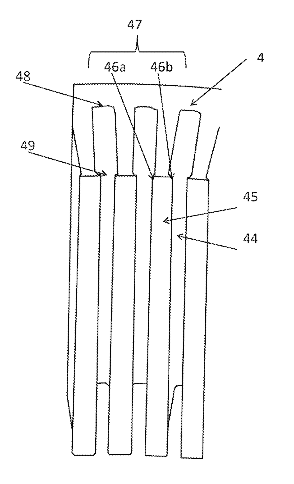
[0097]the tool for the notches 41, 42 and 43 is identical. According to an example of this embodiment, if only one relative rotation of the stator takes place in relation to the tool, there are then the closure elements 451, 452a, 453, 454, 455 and 452b which are situated on the same radial plane. There is then in particular a single closure element 452 formed by the two elements 452a and 452b.

embodiment 2

[0098]the tools for the notches 42 and 43 are different. According to an example of this embodiment, there are then the closure elements 453 and 454 on the one hand, and 455 and 452b on the other hand, which are situated in sets of two, on two different radial planes.

embodiment 3

[0099]the tool for the notches 41 and 43 is identical. According to an example of this embodiment, if there is only one relative rotation of the stator in relation to the tool, there are then the closure elements 451, 452a, 455 and 452b which are situated on the same radial plane, whereas the closure elements 453 and 454 are for example situated on another radial plane. This therefore prevents the aforementioned phenomenon of interference. Also, a single closure element 452 is obtained, formed by the two elements 452a and 452b.

[0100]As already stated for FIGS. 7 and 8, it will be appreciated that N tools 60 could also be provided, distributed axially on the notch 43, which would then give rise to the formation of a maximum of 2 N closure elements distributed axially. There would also be better compacting of the winding part 53 of the notch 43, thanks to the radial supports distributed axially.

[0101]FIG. 10 illustrates N=2 tools for the notches 41 and 43 and N=1 tool for the notch 4...


PUM


Abstract

A stator of a rotary electrical machine has a stator body formed by a stack of metal sheets. The stator body is delimited by inner and outer radial surfaces. Notches in the stator body extend axially. Each notch has a notch base and a notch opening, and the notch opening is on the side of the inner radial surface. A stator winding is supported by the stator body, and the winding has a plurality of winding parts. Each part is accommodated in one of the notches. Each of the notches at the notch opening has a closure element. Each winding par in a notch is retained between the notch base and the closure element. The closure elements are formed by offsetting at least one of the metal sheets of an adjacent notch in the direction of the notch.

Description

CROSS-REFERENCE TO RELATED APPLICATIONS AND CLAIM TO PRIORITY[0001]This application is related to Patent Application No. 1560709 filed Nov. 9, 2015 in France, the disclosure of which is incorporated herein by reference and to which priority is claimed.FIELD OF THE INVENTION[0002]The present invention relates to a rotary electrical machine, and more particularly to the stator of a rotary electrical machine of this type.BACKGROUND OF THE INVENTION[0003]Use of rotary electrical machines in motor vehicles is known. These can consist of a compact polyphase alternator. This alternator transforms mechanical energy into electrical energy, and can be reversible. A reversible alternator of this type is known as an alternator-starter, and in another functioning mode transforms electrical energy into mechanical energy, in particular in order to start the thermal engine of the vehicle.[0004]This machine substantially comprises a housing 1, and, inside the latter, a claw rotor 2 which is integral...

Claims


Application Information

Patent Timeline
Patent Type & Authority Applications(United States)
IPC IPC(8): H02K1/16H02K3/487H02K15/00
CPCH02K1/165H02K3/487H02K15/0031H02K2213/03H02K3/48H02K15/0018H02K1/12H02K3/521
Inventor BILTERYST, PIERRE-YVESDELIANNE, HENRIMARGUERITTE, DAVIDJOZEFOWIEZ, ERICPERREAUT, SYLVAINBALTHAZE, PATRICEBATTUT, JULIEN
Owner VALEO EQUIP ELECTRIC MOTEUR
Why Eureka
Try Eureka