Positive expiratory pressure devices with flutter valve

a technology of expiratory pressure and valve, which is applied in the direction of inhalators, gymnastics, other medical devices, etc., can solve the problems of compromising flow with increased friction, requiring more work to exhale, and patients in need of pep therapy may not generally exhale with enough force to expand the alveoli

Inactive Publication Date: 2017-05-18
RUSHER MICHAEL J
View PDF7 Cites 12 Cited by
  • Summary
  • Abstract
  • Description
  • Claims
  • Application Information

AI Technical Summary

Benefits of technology

[0015]f) a valve in the second passageway that allows air to flow out from the second passageway when a patient using the device exhales with an expiratory air pressure greater than a selected pressure, that prevents air from flowing out through the second passageway when a patient exhales with an expiratory air pressure that is less than that selected air pressure, and that prevents air from flowing in through the second passageway when a patient using the device inhales,

Problems solved by technology

Patients in need of PEP therapy may not generally exhale with enough force to expand the alveoli.
However, known prior art devices use strictures or small orifices to produce positive expiratory pressures.
This may compromise flow with increased friction, requiring more work to exhale.
Additionally, some known PEP devices are useful only for allowing a patient to exhale, and may not be used for normal in-and-out breathing.
In some cases a problem may arise if the pressure in the inspiratory tube rises above a level that is safe for the patient.
This is particularly a problem when the ventilator is operating in a volume control mode, although excessive pressure may arise even when the ventilator is operating in a pressure control mode.

Method used


Image

  • Positive expiratory pressure devices with flutter valve
  • Positive expiratory pressure devices with flutter valve
  • Positive expiratory pressure devices with flutter valve

Examples


Embodiment Construction

[0084]For the purposes of promoting an understanding of the principles of the invention, reference will now be made to certain embodiments and specific language will be used to describe the same. It will nevertheless be understood that no limitation of the scope of the invention is thereby intended, with alterations and modifications being contemplated as would normally occur to persons skilled in the art to which the invention relates.

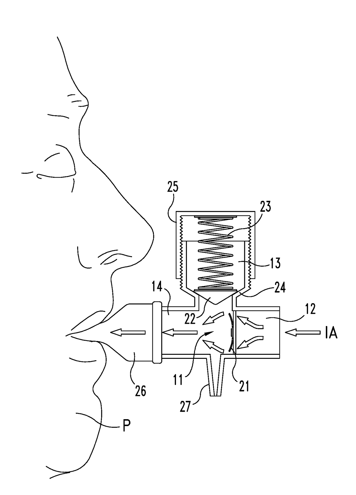
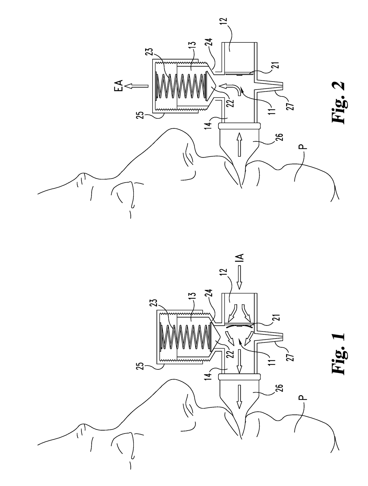
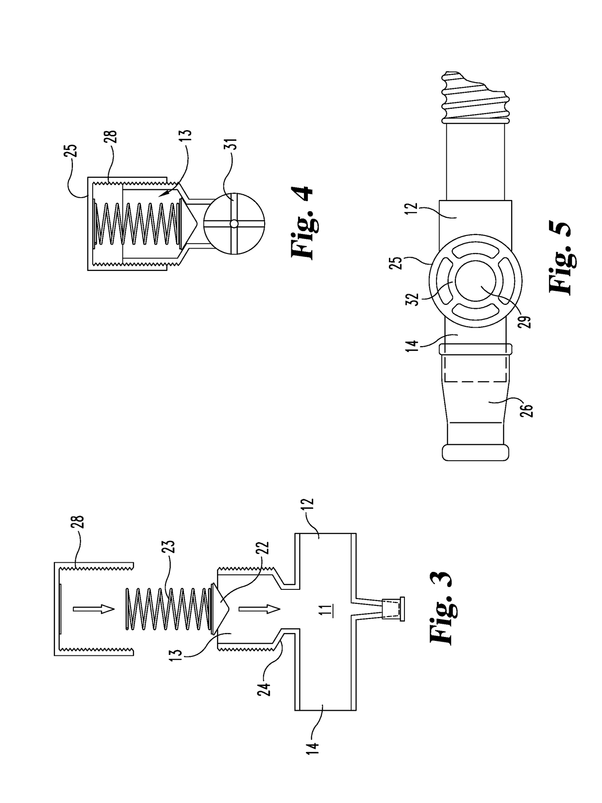
[0085]As indicated above, one aspect of the present invention relates to a device for providing resistance in an air pathway for a patient who is exhaling. In one embodiment the positive pressure airway device comprises:[0086]a) a central tube region;[0087]b) a first passageway for passing air into said central tube region when a patient breathing through the device inhales;[0088]c) a second passageway for passing air out of said central tube region when a patient breathing through the device exhales;[0089]d) a third passageway for passing air from sa...


PUM


Abstract

A positive pressure airway device for providing resistance in an air pathway for a patient exhaling. The device includes a central tube region, a inspiratory air passageway for passing air into the central tube region when a patient breathing through the device inhales, and an expiratory air passageway for passing air out of the central tube region when a patient breathing through the device exhales, A valve in the expiratory air passageway allows air to flow out only when a patient using the device exhales with an expiratory air pressure greater than a selected pressure, and includes a stopper and a coil spring with an interior portion that is free from any structure that would inhibit the “side-to-side” movement of the spring within the housing. The stopper has a cone-shaped air-stopping surface providing a valve angle that is different from, and is preferably slightly less than, the valve-seat angle.

Description

REFERENCE TO RELATED APPLICATIONS[0001]This application claims the benefit of U.S. patent application Ser. No. 14 / 175,385, filed Feb. 7, 2014, which claims the benefit of U.S. Provisional Patent Application Ser. No. 61 / 761,938, filed Feb. 7, 2013, and of U.S. patent application Ser. No. 13 / 459,564, filed Apr. 30, 2012, and of U.S. Provisional Patent Application Ser. No. 61 / 480,097, filed Apr. 28, 2011. The entire contents of each of the foregoing is incorporated into this application by reference.FIELD OF THE INVENTION[0002]This application relates generally to airway pressure control devices, and more particularly to a positive expiratory pressure device with an oscillating pressure valve to control expiratory air flow.BACKGROUND[0003]Patients that have compromised lungs due to decreased lung capacity resulting from COPD (Chronic Obstructive Pulmonary Disease), CHF (Congestive Heart Failure), or Pulmonary Edema, atelectasis, and / or decreased lung capacity due to pain or inhibited a...

Claims


Application Information

Patent Timeline
Patent Type & Authority Applications(United States)
IPC IPC(8): A61M16/20A61M16/10A61M16/08
CPCA61M16/208A61M16/10A61M16/0875A61M11/06A63B21/023A63B21/05A63B21/0604A63B23/18A61M2202/0208A63B2213/005A63B21/00069A61M16/0833A61M15/0016A61M16/0006A61M16/0866
Inventor RUSHER, MICHAEL J.
Owner RUSHER MICHAEL J
Why Eureka
Try Eureka