Non-pneumatic tire
a tire and non-pneumatic technology, applied in the field of non-pneumatic tires, can solve the problems that the occurrence of tire puncture is a structurally inevitable problem, and achieve the effect of preventing deterioration of vehicle maneuverability and improving ground contact performan
- Summary
- Abstract
- Description
- Claims
- Application Information
AI Technical Summary
Benefits of technology
Problems solved by technology
Method used
Image

Examples
first embodiment
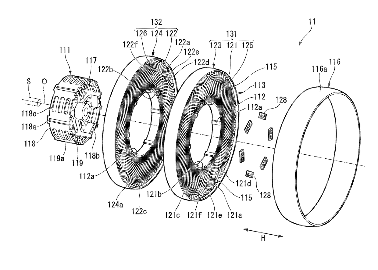
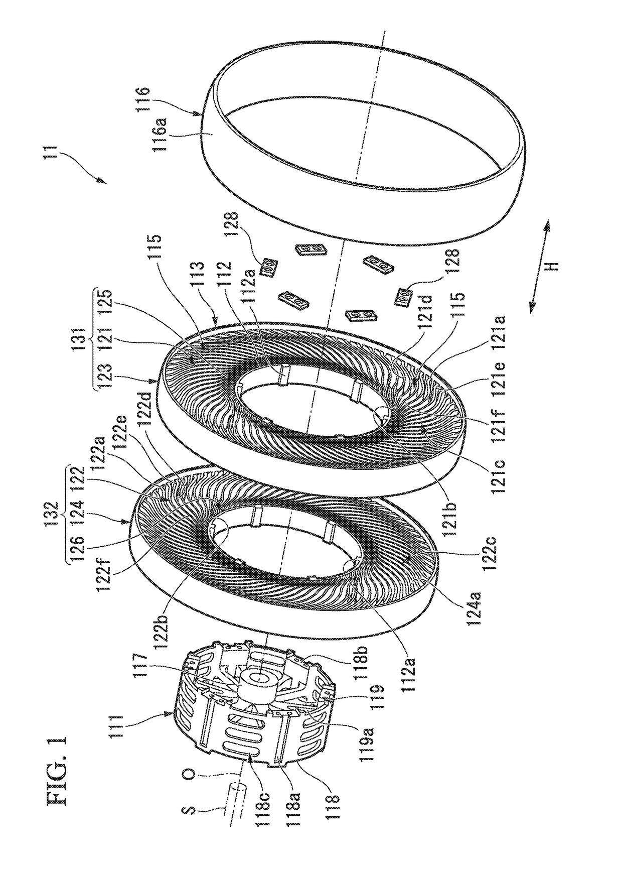
[0048]Hereinafter, a non-pneumatic tire of the present invention is described with reference to FIGS. 1 to 5. A non-pneumatic tire 11 of this embodiment may be employed for, for example, a small-sized vehicle that runs at a low speed such as a handle-type electric wheelchair provided in JIS T 9208. In addition, the size of the non-pneumatic tire 11 of this embodiment may be set to, for example, 3.00-8.
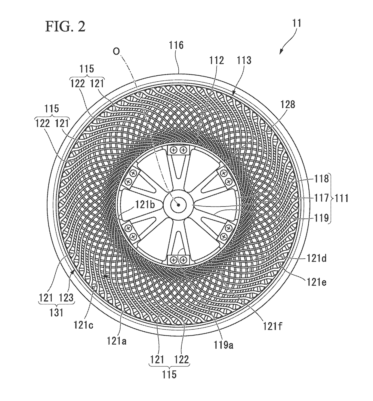
[0049]As shown in FIGS. 1 and 2, the non-pneumatic tire 11 of this embodiment includes a mount body 111 that is mounted on an axle S (a shaft), a ring-shaped body 113 (an outer cylindrical body) encircling the mount body 111 from outside of the mount body 111 in the radial direction of the tire, connecting members 115 arranged in the circumferential direction of the tire between the mount body 111 and the ring-shaped body 113 and connecting the mount body 111 and the ring-shaped body 113 such that the mount body 111 and the ring-shaped body 113 are resiliently movable relative to each ...
sixth embodiment
[0134]Hereinafter, a non-pneumatic tire of the present invention is described with reference to the drawings. The structure of each part of the non-pneumatic tire is not limited to the following description.
[0135]As shown in FIG. 12, a non-pneumatic tire (hereinafter, simply referred to as the “tire”) 21 includes a mount body 23 that is mounted on an axle S (a shaft), an outer cylindrical body 25 encircling the mount body 23 from outside of the mount body 23 in the radial direction of the tire, connecting members 27 arranged in the circumferential direction of the tire between the mount body 23 and the outer cylindrical body 25 and connecting the mount body 23 and the outer cylindrical body 25 such that the mount body 23 and the outer cylindrical body 25 are resiliently movable relative to each other, and a tread portion 29 encircling the outer cylindrical body 25 from outside of the outer cylindrical body 25 in the radial direction of the tire. In addition, in this example, an inne...
seventh embodiment
[0141]As shown in FIG. 14, in the present invention, the thickness t3 in the tire radial direction of a joined part 224 between the first and second outer cylindrical bodies 217 and 218 of the outer cylindrical body 25 is greater than the average thickness of the outer cylindrical body 25 in the tire radial direction, whereby the contact area through which the first and second outer cylindrical bodies 217 and 218 are joined together is increased, and thus the joint strength through welding, adhesion or the like can be improved.
[0142]As shown in FIG. 14, it is preferable that the thickness in the tire radial direction of the outer cylindrical body 25 between the first resilient connecting plate 221 that is a connecting member being close to the first area next to the tire and the second resilient connecting plate 222 that is a connecting member being close to the second area next to the tire, namely the thickness in the tire radial direction of the outer cylindrical body 25 within a ...
PUM
 Abstract
Description
Claims
Application Information
 - R&D Engineer
- R&D Manager
- IP Professional
- Industry Leading Data Capabilities
- Powerful AI technology
- Patent DNA Extraction
Browse by: Latest US Patents, China's latest patents, Technical Efficacy Thesaurus, Application Domain, Technology Topic.
© 2024 PatSnap. All rights reserved.Legal|Privacy policy|Modern Slavery Act Transparency Statement|Sitemap