Article Transfer Device and Article Transport Facility

a technology of transfer device and transfer facility, which is applied in the direction of storage device, control system, mechanical conveyor, etc., can solve the problems of increasing reducing and increasing the error between the target rotational speed and the actual rotational speed of the electric motor

Active Publication Date: 2017-05-18
DAIFUKU CO LTD
View PDF3 Cites 9 Cited by
  • Summary
  • Abstract
  • Description
  • Claims
  • Application Information

AI Technical Summary

Benefits of technology

[0017]wherein, when an external force applied condition that an external force that causes a decrease in a rotational speed of the electric motor is applied to the contact member moved by the electric motor is satisfied while the actuation controller is performing a first control for continuously performing a process of providing the electric motor with a command value that depends on an error between an actual rotational speed of the electric motor and a first target rotational speed so as to cause the actual rotational speed to approach the first target rotational speed, then the actuation controller, subsequent to the first control, performs a second control for providing the electric motor with a command value that allows the actual rotational speed to be equal to, and to fall below, the first target rotational speed at a time of the external force applied condition becoming satisfied.
[0018]With the arrangement describe above, when the rotational speed of the electric motor is decreased when the external force applied condition is satisfied while performing the first control, the actuation cont

Problems solved by technology

This causes the actual rotational speed of the electric motor to decrease, which in turn causes the error between the target rotational speed and the actual rotational speed of the electric motor to increase.
Furthermore, with the article transfer device described in Patent Docume

Method used


Image

  • Article Transfer Device and Article Transport Facility
  • Article Transfer Device and Article Transport Facility
  • Article Transfer Device and Article Transport Facility

Examples


first embodiment

[0036]The article transfer device in accordance with the first embodiment is described with reference to the drawings.

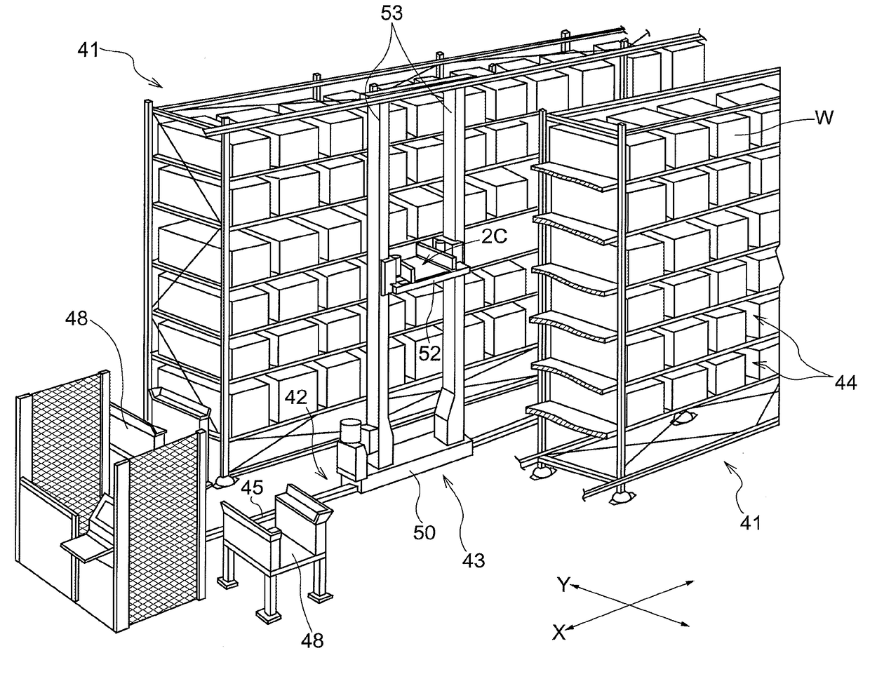
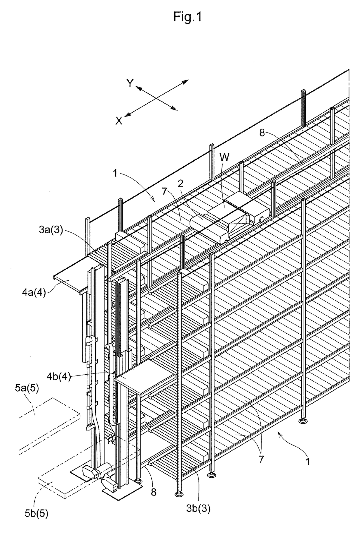
[0037]FIG. 1 is a perspective view of an article transport facility which incorporates an article transfer device 2B. As shown in FIG. 1, the article transport facility has article support portions 1 each of which is configured to support articles, and article transports 2 each of which is capable of moving along its travel path. Each article transport 2 is configured to be capable of delivering articles W, one at a time, to either of the article support portions 1 and receiving articles W, one at a time, from either of the article support portions 1 by moving the article W along a transfer direction by means of its article transfer device 2B at predetermined or preset locations along the travel path.

[0038]As shown in FIG. 1, the article support portions 1 are used to store articles W. Travel rails 8 which define the travel path generally extends linearly along a dir...

second embodiment

[0079]The second embodiment differs from embodiment described above in the content of the second control. In the following description of the article transfer device and the article transport facility of the second embodiment, the structures and arrangements of the second embodiment that are identical or similar to those in the embodiment described above will be omitted.

[0080]FIG. 9 is a drawing for schematically describing the time change in the target rotational speed of the projecting and retracting motor while FIG. 10 is a drawing for schematically describing the time change in the actual rotational speed of the projecting and retracting motor. In the example shown in FIGS. 9 and 10, in the first control performed during a preliminary step for causing the hooks 29a to come into contact with an article W and immediately after the contact, the aim is to get the actual rotational speed of the projecting and retracting motor 22 to be equal to the speed V1a, whereas, in the third con...

third embodiment

[0082]The third embodiment differs from the second embodiment in the content of the second control. In the following description of the article transfer device and the article transport facility of the third embodiment, the structures and arrangements of the third embodiment that are identical or similar to those in the embodiment described above will be omitted.

[0083]FIG. 11 is a drawing for schematically describing the time change in the target rotational speed of the projecting and retracting motor while FIG. 12 is a drawing for schematically describing the time change in the actual rotational speed of the projecting and retracting motor. As shown in FIGS. 11 and 12, during the first control performed in a preliminary step for causing the hooks 29a to come into contact with an article W, the aim is to get the actual rotational speed of the projecting and retracting motor 22 to be equal to the speed V1a, whereas, in the third control which comes after the hooks 29a come into conta...


PUM


Abstract

When an external force applied condition that an external force that causes a decrease in a rotational speed of an electric motor is applied to the contact member moved by the electric motor is satisfied while the actuation controller is performing a first control for continuously performing a process of providing the electric motor with a command value that depends on an error between an actual rotational speed of the electric motor and a first target rotational speed so as to cause the actual rotational speed to approach the first target rotational speed, then the actuation controller, subsequent to the first control, performs a second control for providing the electric motor with a command value that allows the actual rotational speed of the motor to be equal to, and to fall below, the first target rotational speed at a time of the external force applied condition becoming satisfied.

Description

CROSS-REFERENCE TO RELATED APPLICATION[0001]This application claims priority to Japanese Patent Application No. 2015-226008 filed Nov. 18, 2015, the disclosure of which is hereby incorporated in its entirety by reference.FIELD OF THE INVENTION[0002]The present invention relates to an article transfer device configured to move an article along a transfer direction and an article transport facility having such an article transfer device.BACKGROUND[0003]JP Publication of Application No. 2004-203546 (Patent Document 1) describes an article transfer device for moving articles along a transfer direction. More specifically, the article transfer device described in Patent Document 1 includes a contact member that contacts an article and moves the article by moving along the transfer direction, an actuating mechanism which includes an electric motor for moving the contact member along the transfer direction, and an actuation controller which controls the action of the actuating mechanism. An...

Claims


Application Information

Patent Timeline
IPC IPC(8): B65G1/04H02P31/00B65G1/06
CPCB65G1/0492B65G1/06H02P31/00B65G1/04B65G35/00B65G1/0435B65G2203/0266B65G1/0414B65G1/065
Inventor KOIDE, HIROYUKI
Owner DAIFUKU CO LTD
Why Eureka
Try Eureka