Method Of Measuring Time Of Flight Of An Ultrasound Pulse

a technology of ultrasound pulse and measurement method, which is applied in the direction of fluid speed measurement, measurement devices, instruments, etc., can solve the problems of complex method, high computational cost, inaccurate measurement in harsh environments

Active Publication Date: 2017-05-18
POLLUTION CONTROL & MEASUREMENT EURO
View PDF15 Cites 6 Cited by
  • Summary
  • Abstract
  • Description
  • Claims
  • Application Information

AI Technical Summary

Benefits of technology

[0010]The present invention seeks to mitigate the above-mentioned problems. Alternatively or additionally,

Problems solved by technology

However, the technique is dependent on an unchanging medium which would be expected to render the measurement inaccurate in harsh enviro

Method used


Image

  • Method Of Measuring Time Of Flight Of An Ultrasound Pulse
  • Method Of Measuring Time Of Flight Of An Ultrasound Pulse
  • Method Of Measuring Time Of Flight Of An Ultrasound Pulse

Examples


Embodiment Construction

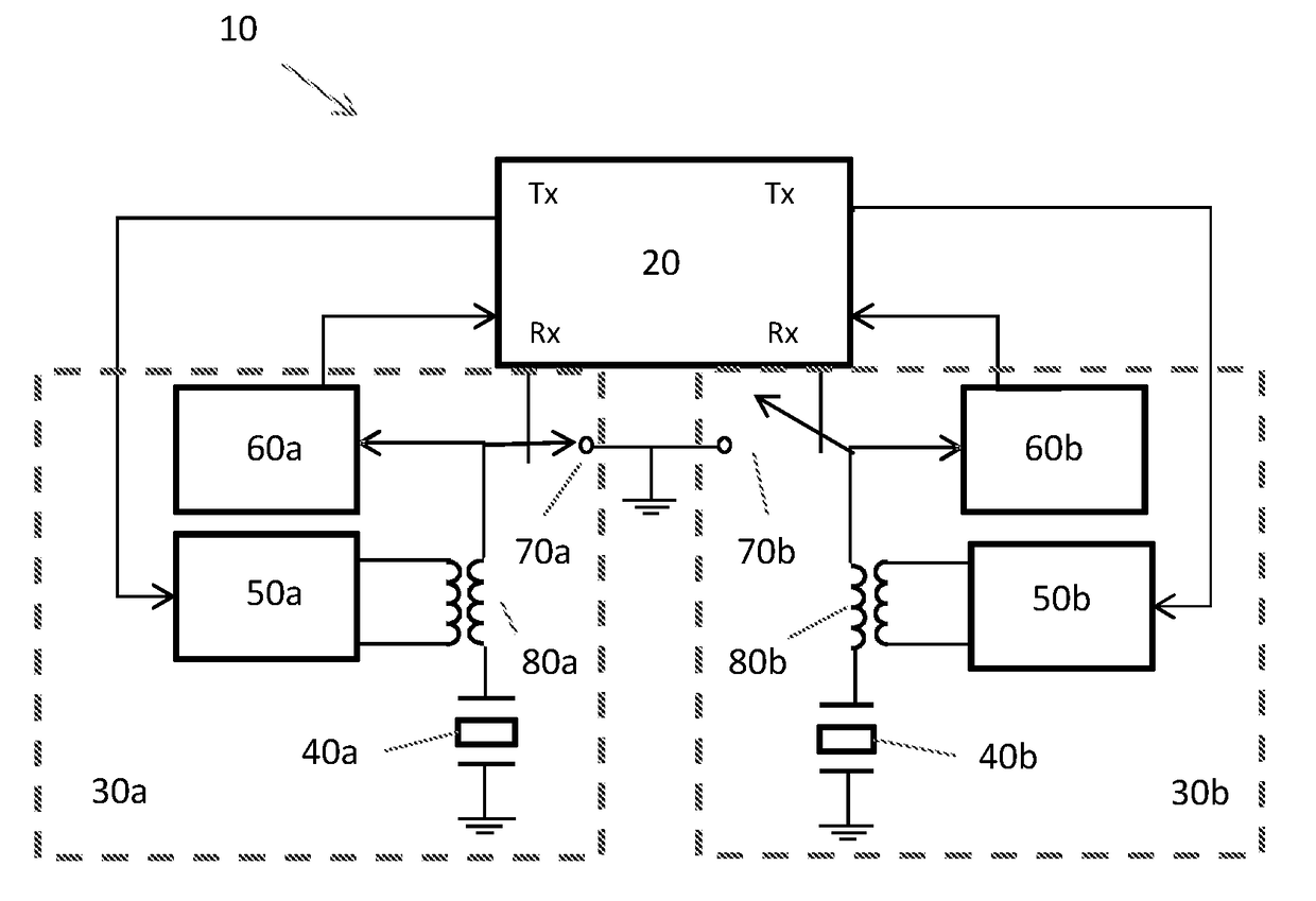
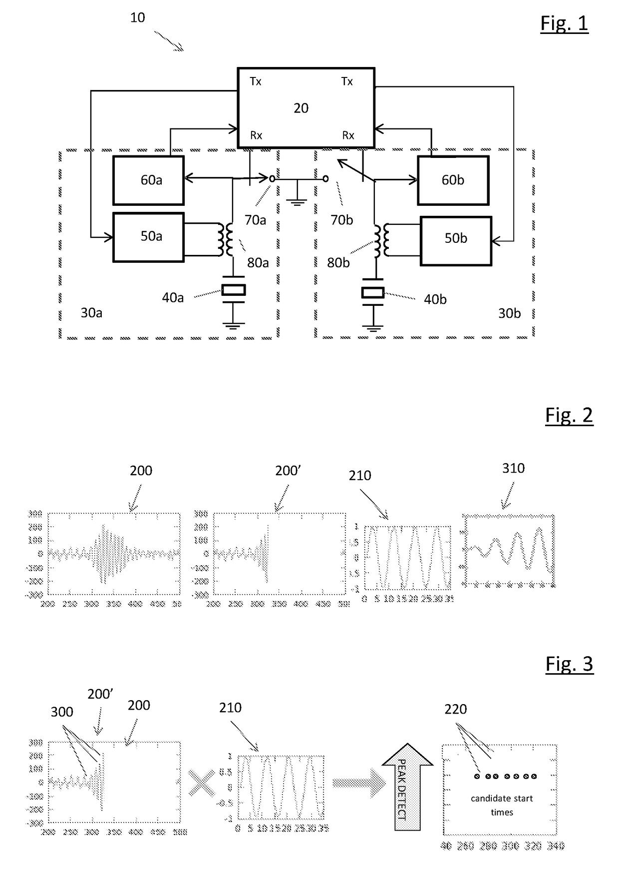
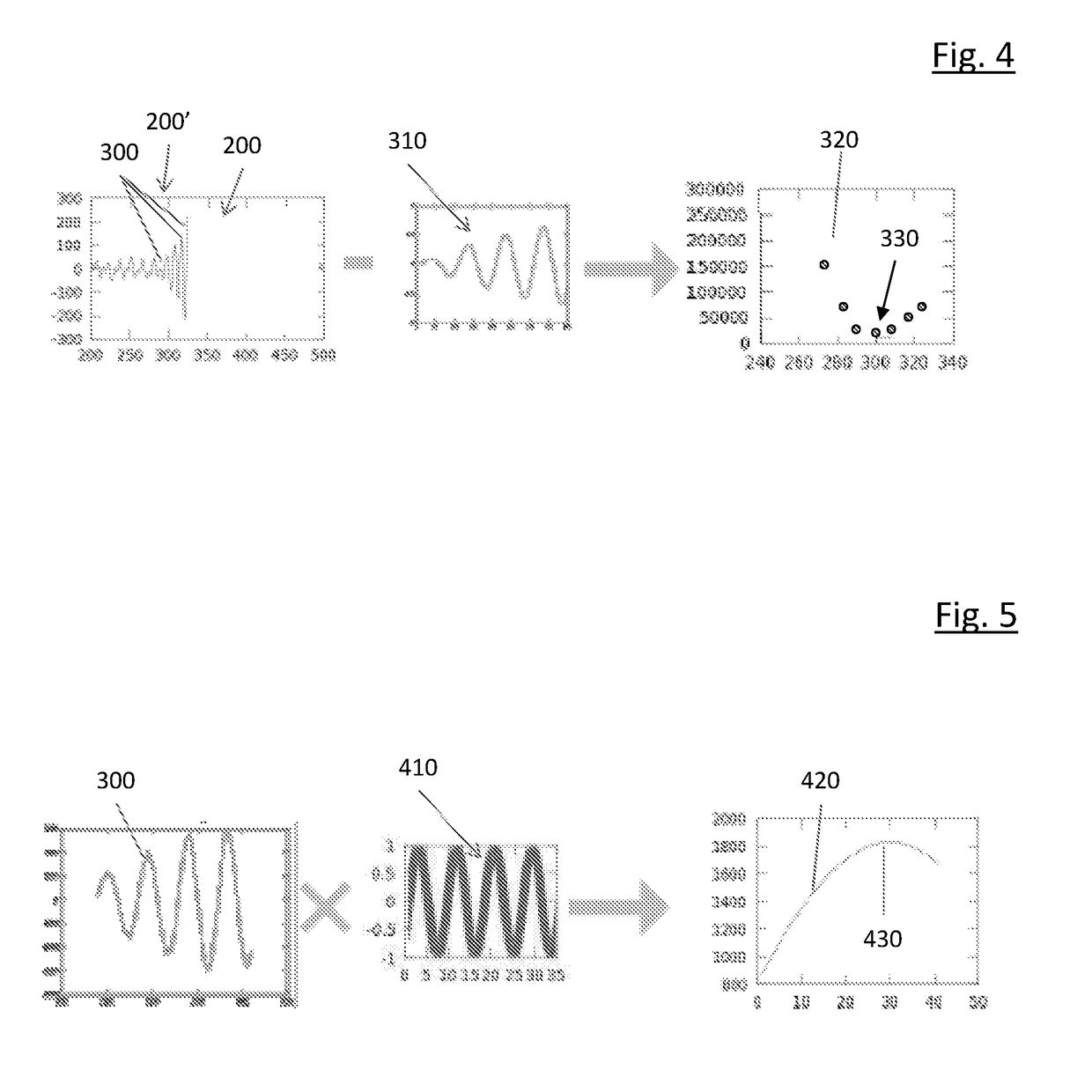
[0042]In one aspect, the invention provides a method of measuring time of flight of a pulse of ultrasound in a fluid flow. The pulse has an ultrasonic frequency. The ultrasound pulse is transmitted across the fluid flow. The ultrasound pulse is detected after transmission, the detected pulse being a waveform. A cross-correlation between the waveform and a tone at the ultrasonic frequency is generated and a plurality of peaks in the cross-correlation are identified. A curve template is fitted to the waveform at temporal locations corresponding to the peaks in the cross-correlation. The temporal location in the waveform of the minimum error of the fit is identified. A further cross-correlation between the waveform and the tone is performed, the further cross-correlation being carried out over only a portion of the waveform, the portion containing the temporal location corresponding to the minimum error of the fit. The temporal location in the waveform corresponding to the maximum of t...


PUM


Abstract

Method and apparatus relating to ultrasound flow probes Measurement of time of flight of ultrasound pulses comprises: transmitting the pulses across a fluid flow; detecting a waveform (200) of the pulses, generating a cross-correlation between the waveform (200) and a tone (210) and identifying a plurality of peaks (220) in the cross-correlation; fitting a curve template (310) to the waveform at locations (300) corresponding to the peaks (220) and identifying the location (330) of the minimum error; performing a further cross-correlation (420) between the waveform (200) and the tone (210) over only a portion of the waveform (200) containing the minimum error location (330); and determining the temporal location corresponding to the maximum (430) of the further cross-correlation (430).

Description

FIELD OF THE INVENTION[0001]The present invention concerns an ultrasound flow probe and methods of monitoring fluid flow using ultrasound pulses. More particularly, but not exclusively, this invention concerns a method of measuring time of flight of ultrasound pulses in a fluid flow, a method of measuring the flow velocity of a fluid flowing in a conduit, for example a stack, an ultrasound flow probe for measuring the flow velocity of a fluid flowing in a conduit, and a stack including an ultrasound flow probe.BACKGROUND OF THE INVENTION[0002]It is often desirable to know the characteristics of fluid flow in a conduit, for example a stack. That may be, for example, due to a regulatory requirement to monitor emissions or a desire to improve the efficiency of an industrial process. Characteristics of fluid flow being measured can include: the average velocity of the fluid, the velocity profile of the fluid, and / or any departure from laminar flow within the fluid.[0003]There is a varie...

Claims


Application Information

Patent Timeline
IPC IPC(8): G01F1/66
CPCG01F1/662G01F1/667G01F23/2962G01P5/248
Inventor D'SOUZA-MATTHEW, NEILFRYERS, ROBERTMILLINGTON, ROGERUNITT, DAVID
Owner POLLUTION CONTROL & MEASUREMENT EURO
Why Eureka
Try Eureka