Method of soil liquefaction testing and remediation

a soil liquefaction and remediation technology, applied in earth material testing, construction, foundation engineering, etc., can solve the problems of repeated shearing deformation in overlying soil, liquefaction in saturated cohesionless, and hundreds of miles of destructive energy

Inactive Publication Date: 2017-05-18
ELLINGTON JONATHAN SCOTT
View PDF2 Cites 6 Cited by
  • Summary
  • Abstract
  • Description
  • Claims
  • Application Information

AI Technical Summary

Benefits of technology

[0012]A method of soil liquefaction testing and remediation and devices for accomplishing the method are described. Potentially liquefiable soil deposits are subjected to mechanically produced shear strain reversals. Excess pore water pressure generation is monitored at multiple depths and at multiple locations at the site during application of the mechanically produced shear strain reversals to determine actual liquefaction susceptibility of the soil deposit. Multiple ground improvements are positioned on the site mitigate liquefaction in those soils that are determined to be susceptible to liquefaction.

Problems solved by technology

Large earthquakes are capable of generating elastic stress waves that carry destructive amounts of energy for hundreds of miles.
When stress waves travel through the earth's crust (bedrock), they result in repeated shearing deformations in overlying soils.
The resulting shearing deformations are the principal cause of liquefaction in saturated cohesionless (sandy) soils.
The continued shaking of the jar will cause the loose marbles to “collapse” into a tighter nesting / packing.
This phenomenon is known as liquefaction, and is responsible for extensive damage in earthquakes.
The liquefied deposit is often unable to support the loads imposed on it from structures and works.
Historically, liquefaction has resulted in catastrophic bearing capacity failures.
Because of the relative unpredictability of earthquakes, universities, research institutes and government entities have to rely on stochastic methods to estimate the likelihood of the occurrence of seismic events of varying energies over varying time periods.
Attempting to design for all earthquakes is infeasible.

Method used


Image

  • Method of soil liquefaction testing and remediation
  • Method of soil liquefaction testing and remediation
  • Method of soil liquefaction testing and remediation

Examples


Embodiment Construction

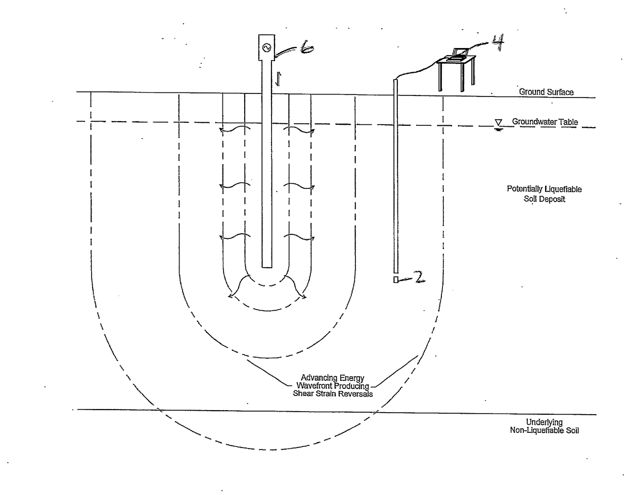
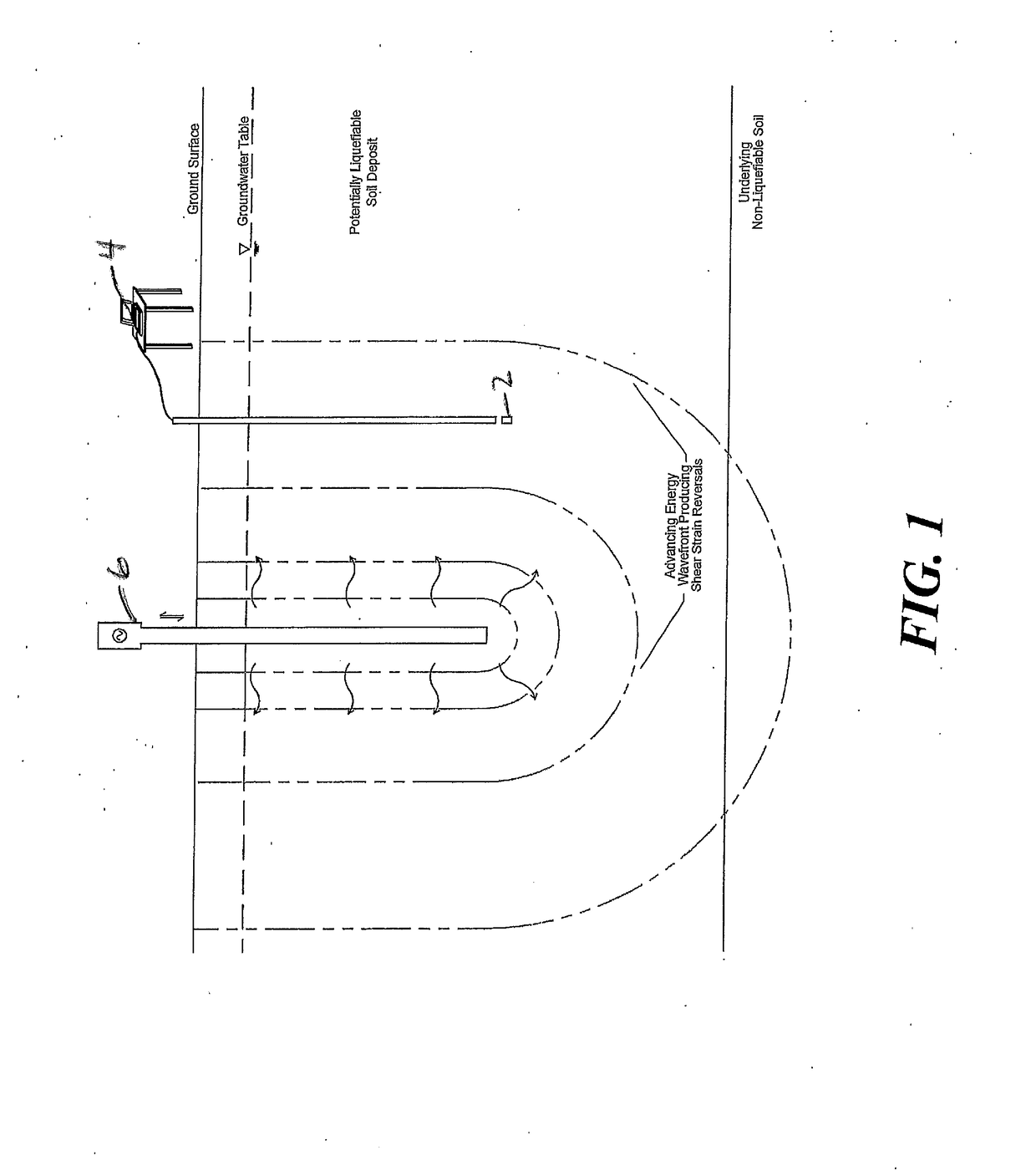
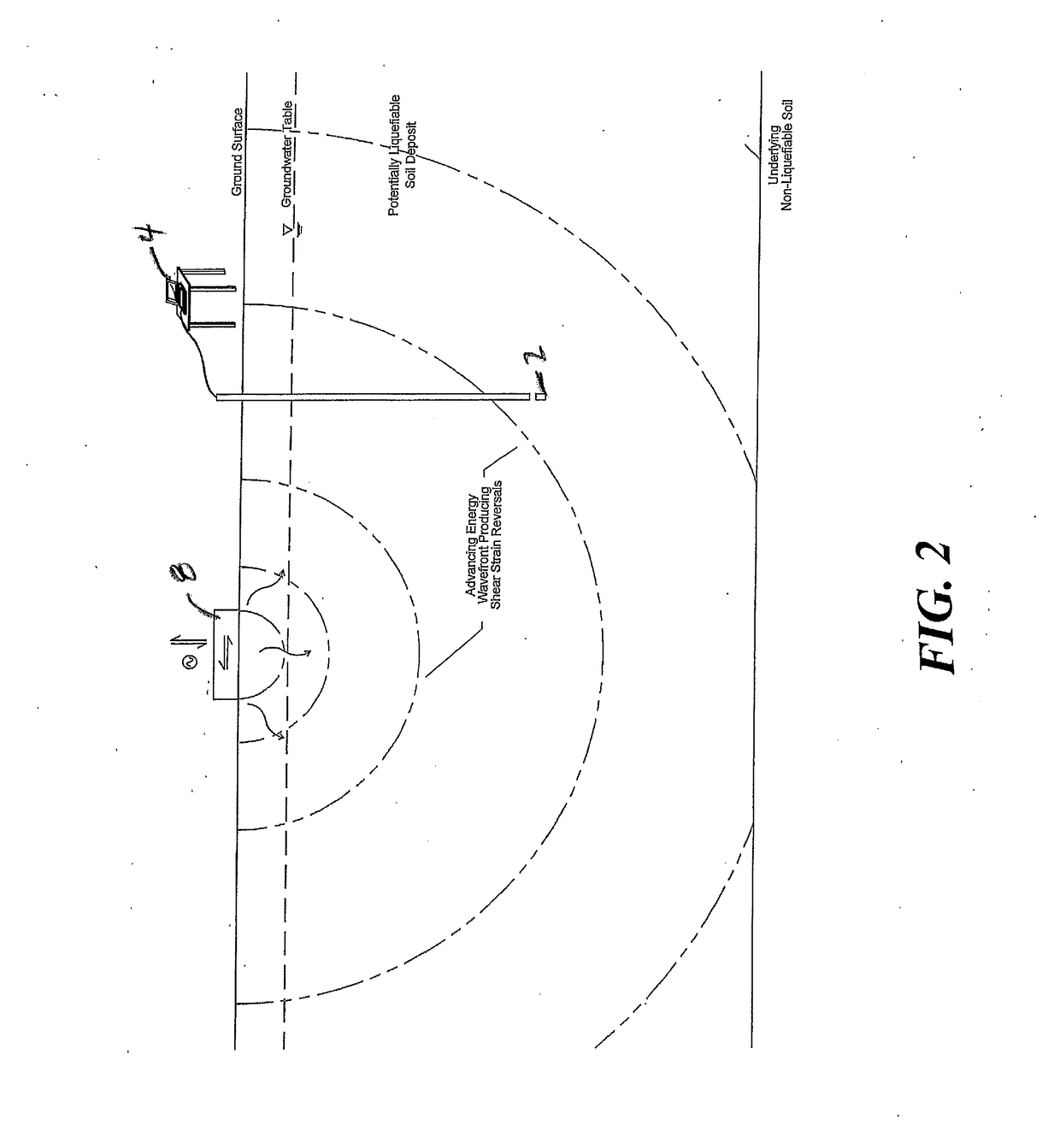
[0021]The apparatus and method of the present invention for testing and subsequent remediation of liquefiable soil for earthquake liquefaction protection for a structure or work thereon involves instrumenting a potentially liquefiable soil deposit with equipment capable of measuring pore water pressure generation / dissipation and shear strain reversals in-situ. Determining that a soil deposit at a site is potentially subject to liquefaction may be based on assumed or estimated soil index properties. The soil deposit is subjected to mechanically-produced shear strain reversals (soil accelerations) in excess of those anticipated from the design seismic event for durations longer than the design seismic event. The shear strain reversals may be produced at varying depths.

[0022]The present invention allows the subject site to be tested and treated according to soil accelerations of varying design earthquakes, (e.g. Moment Magnitudes, MW, ranging from 5.0 to 9.5). The soil accelerations ma...


PUM

PropertyMeasurementUnit
pore pressuresaaaaaaaaaa
frequencyaaaaaaaaaa
pore pressureaaaaaaaaaa

Abstract

A method of soil liquefaction testing and remediation and devices for accomplishing the method are described. After determining that a soil deposit on a site is potentially subject to liquefaction, the soil deposit is subjected to mechanically produced shear strain reversals. Excess pore pressure generations are monitored at multiple depths and at multiple locations at the site, during application of the mechanically produced shear strain reversals, to determine liquefaction susceptibility of the soil deposit. Multiple ground improvements are positioned on the site mitigate liquefaction in those soils that are determined to be susceptible to liquefaction.

Description

[0001]Applicant claims the benefit of U.S. Provisional Patent Application filed Nov. 17, 20, 2015, Ser. No. 62 / 256,297.FIELD OF THE INVENTION[0002]This invention relates generally to the liquefaction testing and remediation of potentially liquefiable soils to minimize damage to supported structures and works from earthquake-induced liquefaction.BACKGROUND OF THE INVENTION[0003]During and after an earthquake (seismic event), energy, in the form of compression, shear and Rayleigh waves, travels radially from the epicenter (focus or origin) of the earthquake in all directions. Large earthquakes are capable of generating elastic stress waves that carry destructive amounts of energy for hundreds of miles.[0004]When stress waves travel through the earth's crust (bedrock), they result in repeated shearing deformations in overlying soils. The resulting shearing deformations are the principal cause of liquefaction in saturated cohesionless (sandy) soils.[0005]When loose cohesionless (sandy) ...

Claims


Application Information

Patent Timeline
Patent Type & Authority Applications(United States)
IPC IPC(8): G01N3/24G01N33/24
CPCG01N3/24E02D2600/10E02D7/00G01N33/24
Inventor ELLINGTON, JONATHAN SCOTT
Owner ELLINGTON JONATHAN SCOTT
Why Eureka
Try Eureka