Cyber physical system

Inactive Publication Date: 2017-05-18
KRIWAN IND ELEKTRONIK
View PDF0 Cites 19 Cited by
  • Summary
  • Abstract
  • Description
  • Claims
  • Application Information

AI Technical Summary

Benefits of technology

[0006]Therefore the object of the present invention is to improve upon the secu

Problems solved by technology

The cyber physical system is therefore visible on the Internet only for the brief instant

Method used


Image

  • Cyber physical system
  • Cyber physical system

Examples


Embodiment Construction

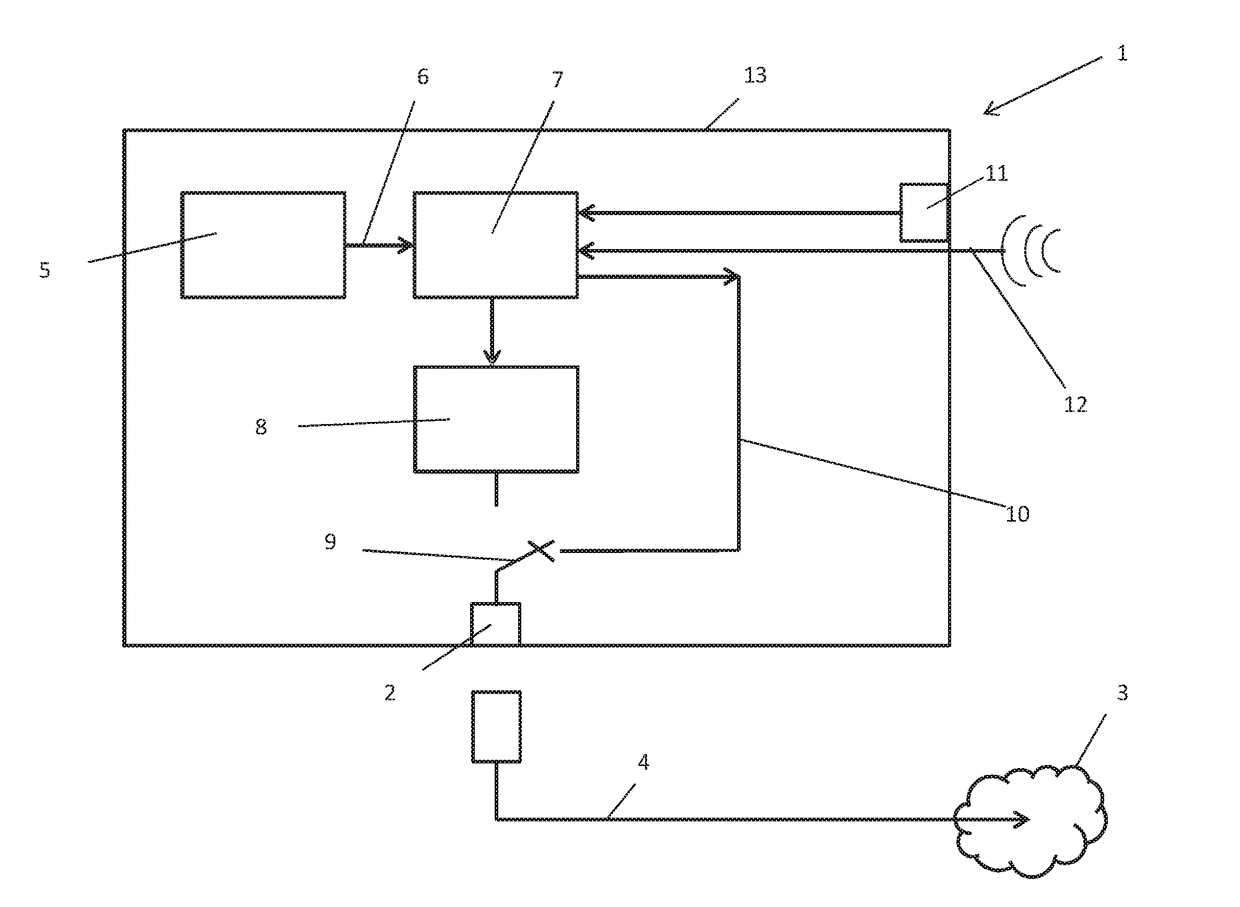
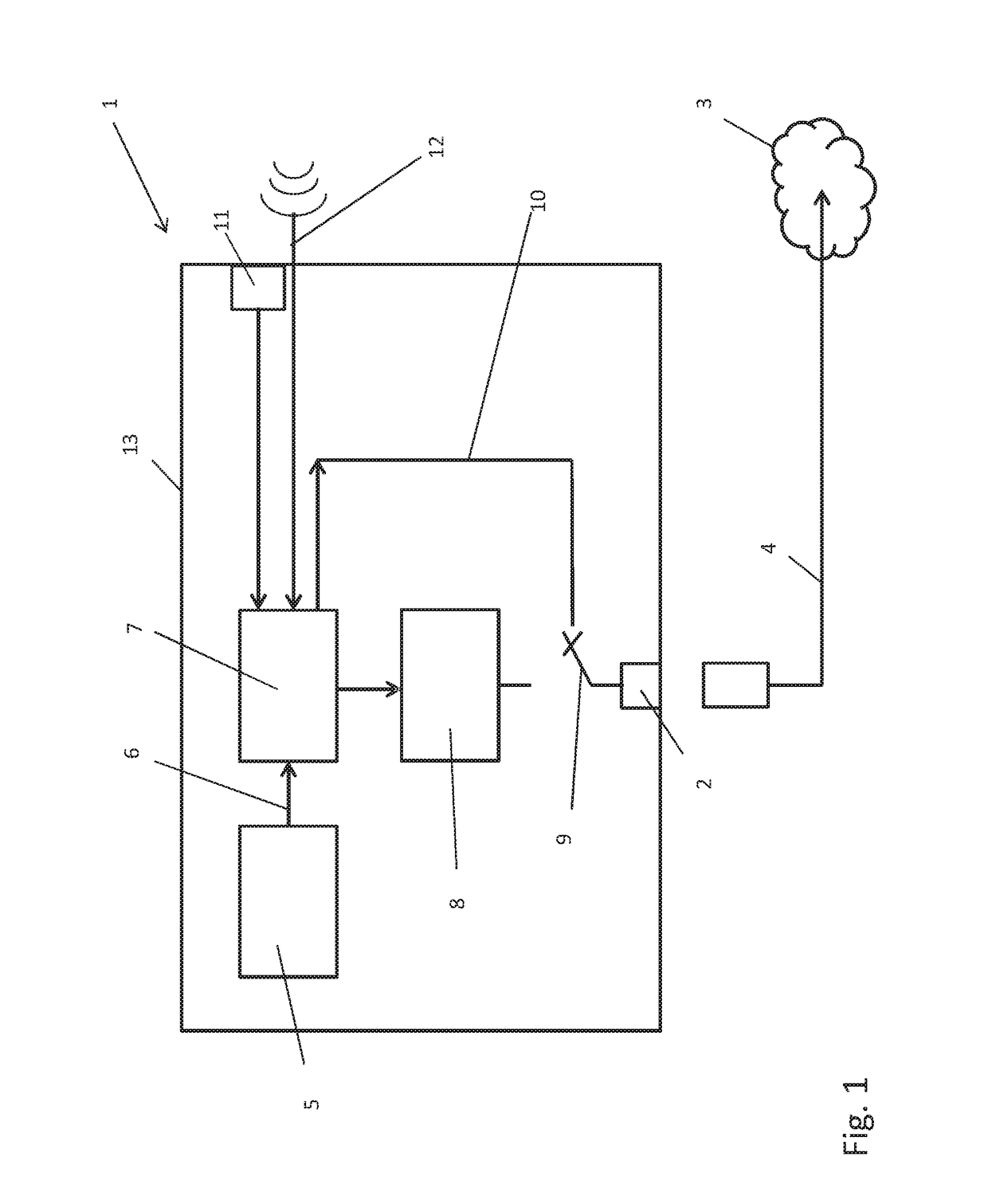
[0017]The cyber physical system 1 also has a transmission and / or reception unit 8 for transmitting and / or receiving data over the Internet, wherein the connection between the transmission unit 8 and the hard-wired interface 2 is physically disconnected by a controllable switch 9 during normal operation of the cyber physical system. However, the controllable switch 9 can be controlled by a control unit 7 over an Internet line 10 in the sense of closing the controllable switch and thus in the sense of enabling the connection between the cyber physical system 1 and the Internet 3. It is thus possible to provide in particular that the connection is enabled by a certain event, for example, in a predefined time window for monitoring and / or maintenance work. However, it is also conceivable for enabling to be triggered by an operating on site in particular by means of an input device 11 or by means of an external channel 12, in particular by means of a mobile cellular connection.

[0018]After...


PUM


Abstract

A cyber physical system including at least one monitoring and safety device for monitoring various parameters of a machine with regard to the maintenance of setpoint values and for generating an error signal in the event of an error and a hard-wired interface to the Internet and a transmission and/or reception unit for transmitting and/or receiving data over the Internet, wherein the monitoring or safety device is connected to the transmission and/or reception unit for transmitting the error signal over the Internet. The hard-wired interface is connected to a controllable switch for physical disconnection and enabling of the connection between the cyber physical system and the Internet, and the cyber physical system has at least one control unit connected to the monitoring or control device for triggering the controllable switch for brief enabling of the connection between the cyber physical system and the Internet.

Description

TECHNICAL FIELD[0001]The invention relates to a cyber physical system with a hard-wired interface to the Internet and a transmission and / or reception unit for transmitting and / or receiving data over the Internet.BACKGROUND[0002]A cyber physical system is understood to be a network of informational software components with mechanical and electronic components connected to the Internet.[0003]It is customary in industrial plants for the individual units that are used to be connected to a control station, from which the processes taking place can be controlled. Any error messages of the units being monitored also converge in the control station. With smaller systems or machines not connected to a control station, any error signals are displayed on the machines themselves or on a respective control box. In many cases there is also the option of forwarding these errors to authorized persons over the Internet. However, an Internet connection always also entails the risk of hacker attacks o...

Claims


Application Information

Patent Timeline
IPC IPC(8): G06F11/07H04L29/06H04L12/28
CPCG06F11/0772H04L12/2867G06F11/0751G06F11/0709H04L63/04H04L41/14G06F21/552
Inventor ELLWEIN, CHRISTIAN
Owner KRIWAN IND ELEKTRONIK
Why Eureka
Try Eureka