System and method for cutting material in continuous fiber reinforced additive manufacturing

a technology of additive manufacturing and continuous fiber reinforcement, applied in the direction of additive manufacturing processes, manufacturing tools, layer means, etc., can solve the problems of insufficient separation of feedstock from extruder, simple halting of fiber reinforced feedstock, and impracticality of cutting manually or by typical cutting devices

Active Publication Date: 2017-05-25
THE BOEING CO
View PDF2 Cites 109 Cited by
  • Summary
  • Abstract
  • Description
  • Claims
  • Application Information

AI Technical Summary

Benefits of technology

[0007]In some embodiments, the cutting mechanism comprises a ribbon including one or more perforations. A feedstock is passed through at least one perforation of the one or more perforations and movement of the ribbon cuts the feedstock. In some embodiments, the cutting mechanism may comprise one or more sharpened edges outlining each perforation. In further embodiments, the one or more perforations may be substantially teardrop shaped with respect to one direction. In other embodiments, the one or more perforations may be symmetrically shaped. In some embodiments, the cutting device may further comprise a set of rotatable reels coupled to the ribbon, and rotating at least one of the reels causes movement of the ribbon in one or more directions. In some embodiments, the cutting device may further comprise one or more motors coupled to at least one reel, and the one or more motors causes at least one reel to rotate. In other embodiments the cutting device may further comprise one or more guides. The ribbon passes through the one or more guides and remains within a predetermined space defined by the one or more guides. In some embodiments, each movement of the ribbon may cause at least one perforation to substantially align with at least one opening of an extruder in a fused deposition modeling system. In some embodiments, the extruder may include one or more openings. In some embodiments, the feedstock may comprise a continuous carbon fiber or other continuous fiber reinforced composite.
[0008]In yet another embodiment, the cutting mechanism comprises a disk including one or more blade structures. Each blade structure includes at least one cavity. A feedstock is passed through at least one cavity and a rotational movement of the disk cuts the feedstock. In some embodiments, the cutting mechanism may include one or more sharpened edges outlining each cavity. In further embodiments, one or more cavities may be substantially teardrop shaped with respect to one direction. In other embodiments, at least one cavity may comprise at least one fully enclosed perforation with each blade structure. In some embodiments, the cutting device may further comprise one or more motors coupled to the disk, and the one or motors causes the disk to rotate. In other embodiments, each rotational movement of the disk may cause at least one cavity to substantially align with at least one opening of an extruder in a fused deposition modeling system. In some embodiments, the extruder may include one or more openings. In some embodiments, the feedstock may comprise a continuous carbon fiber or other continuous fiber reinforced composite.
[0009]In yet another embodiment, the cutting mechanism comprises a guide shaft including a set of rails positioned in parallel. A feedstock is passed between the rails. The cutting device may further comprise a slider coupled to the rails such that the slider may move along a length of the rails from a first position to a second position. The cutting device may further comprise a crank mechanism coupled to the slider, and rotation of the crank mechanism causes the slider to travel the length of the rails and cut the feedstock passed between the rails. The slider may return to the first position after each full rotation of the crank mechanism. In some embodiments, the cutting mechanism may include one or more sharpened edges. In other embodiments, the cutting mechanism may further include an end structure coupled to the guide shaft. In another embodiment, the cutting mechanism may comprise a set of blade structures including the one or more sharpened edges. The blade structures are coupled to the slider, and the end structure is shaped such that the end structure causes the blade structures to come together and cut the feedstock when the slider is at the second position. In other embodiments, the cutting device may further comprise one or more motors coupled to the crank mechanism, and the one or more motors causes the crank to rotate. In some embodiments, the guide shaft may be substantially aligned with at least one opening of an extruder in a fused deposition modeling system. In some embodiments, the extruder may include one or more openings. In some embodiments, the feedstock may comprise a continuous carbon fiber or other continuous fiber reinforced composite.
[0010]In yet another embodiment, the cutting mechanism comprises one or more blade structures, each blade structure including at least one cavity. The cutting mechanism further comprises at least one rod coupled to at least one blade structure such that the blade ...

Problems solved by technology

For example, if the extruded material is a fiber reinforced feedstock, simply halting of the fiber reinforced feedstock is insufficient for separating the feedstock from the extruder.
However,...

Method used


Image

  • System and method for cutting material in continuous fiber reinforced additive manufacturing
  • System and method for cutting material in continuous fiber reinforced additive manufacturing
  • System and method for cutting material in continuous fiber reinforced additive manufacturing

Examples


example embodiments

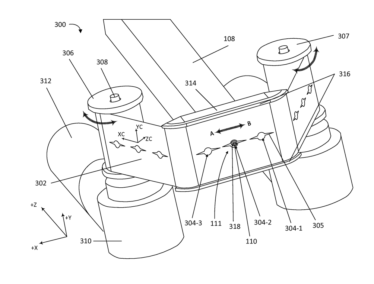
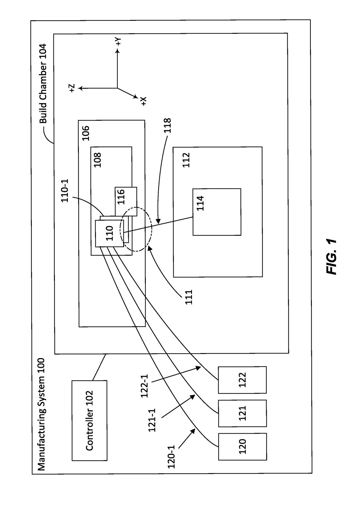
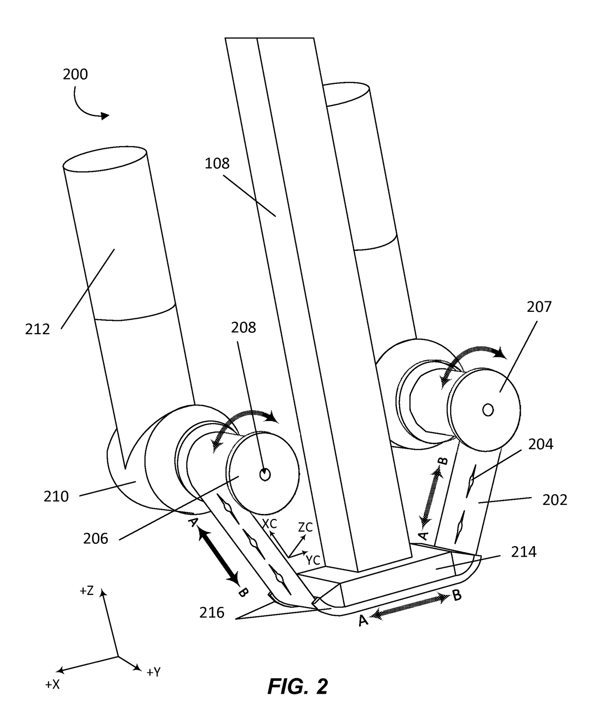
[0064]FIG. 1 illustrates an example of a manufacturing system that can be used in conjunction with the various techniques and embodiments of the present disclosure. According to various embodiments, manufacturing system 100 may include controller 102, build chamber 104, robotic mechanism 106, extruder 108, opening 110, opening 110-1, feedstock pass through zone 111, moveable table 112, object 114, cutting device 116, extruded material 118, material source 120, material feedstock 120-1, material source 121, material feedstock 121-1, material source 122, and material feedstock 122-1. In accordance with various embodiments, manufacturing system 100 may be a fused deposition modeling system configured to build a three dimensional object depicted as object 114. In some embodiments, controller 102 may be a computer system with memory and one or more processors configured to control various manufacturing processes including, but not limited to material input, robotic arm movement, extruder...


PUM

PropertyMeasurementUnit
Lengthaaaaaaaaaa
Angleaaaaaaaaaa
Perimeteraaaaaaaaaa

Abstract

Methods, apparatus, and systems for cutting material used in fused deposition modeling systems are provided, which comprise a ribbon including one or more perforations. Material is passed through at least one perforation and movement of the ribbon cuts the material. A further embodiment comprises a disk including one or more blade structures, each forming at least one cavity. Material is passed through at least one cavity and a rotational movement of the disk cuts the material. A further embodiment comprises a slider-crank mechanism including a slider coupled to a set of parallel rails of a guide shaft. The slider moves along a length of the rails to cut the material. Yet another embodiment comprises one or more rotatable blade structures coupled to at least one rod. The rotation of the blade structures causes the blade structures to intersect and cut extruded material during each rotation.

Description

TECHNICAL FIELD[0001]The present disclosure relates generally to additive manufacturing, and more specifically to the cutting of materials used in such manufacturing systems.DESCRIPTION OF RELATED ART[0002]In many manufacturing processes, materials may need to be shaped through various processes including melting, combining, and / or cutting. For example, fused deposition modeling (FDM), also known as fused filament fabrication (FFF), is an additive manufacturing process commonly used for modeling, prototyping, and production application. Such manufacturing processes are increasingly being used as a technique for 3D printing, modeling, and manufacturing. FDM works on an additive principle by laying down material in layers. A model and / or part is typically produced by extruding small flattened amounts of molten material and / or support material from an extrusion nozzle to form layers as the material hardens after extrusion from the nozzle.[0003]Typically, the material, such as thermopla...

Claims


Application Information

Patent Timeline
IPC IPC(8): B29C67/00B26D3/16B26D1/14B26D1/25B29C70/30B33Y50/02B29C69/00B33Y10/00B33Y70/00B29C70/16B26D5/00B33Y30/00B29C48/04B29C48/05
CPCB29C67/0085B22D11/01B26D3/16B26D1/14B26D1/25B33Y30/00B33Y50/02B29C67/0088B29C69/001B29C67/0081B33Y10/00B33Y70/00B29C70/16B29C70/30B29K2105/10B29K2307/04B29K2105/0067B29K2071/00B26D5/005B29C70/382B29C70/545B26D1/143B26D1/46B26D2001/006B33Y40/00B29C64/165B29C48/02B29C48/266B29C48/345B29C48/0022B29C64/118B29C64/209B29C64/393B29C64/106B29C48/04B29C48/05B29C48/30
Inventor WALDROP, III, JOHN C.BLOCH, DANIEL D.HAYES, MICHAEL W.STRAHM, LOREN J.SZOSTAK, PETER A.
Owner THE BOEING CO
Why Eureka
Try Eureka