Non-contact acoustic inspection method for additive manufacturing processes

a non-contact acoustic inspection and additive manufacturing technology, applied in the field of additive manufacturing, can solve the problems of process requiring undesirable extra time and cost, limited additive manufacturing,

Active Publication Date: 2017-05-25
GENERAL ELECTRIC CO
View PDF11 Cites 25 Cited by
  • Summary
  • Abstract
  • Description
  • Claims
  • Application Information

AI Technical Summary

Problems solved by technology

Unlike casting processes, additive manufacturing is limited only by the position resolution of the machine and not limited by requirements for

Method used


Image

  • Non-contact acoustic inspection method for additive manufacturing processes
  • Non-contact acoustic inspection method for additive manufacturing processes
  • Non-contact acoustic inspection method for additive manufacturing processes

Examples


Embodiment Construction

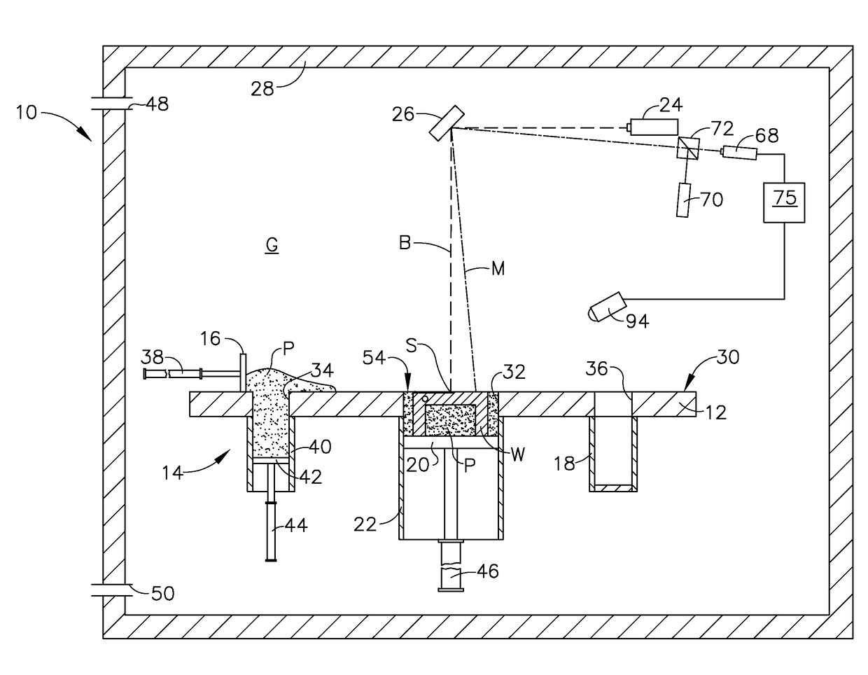
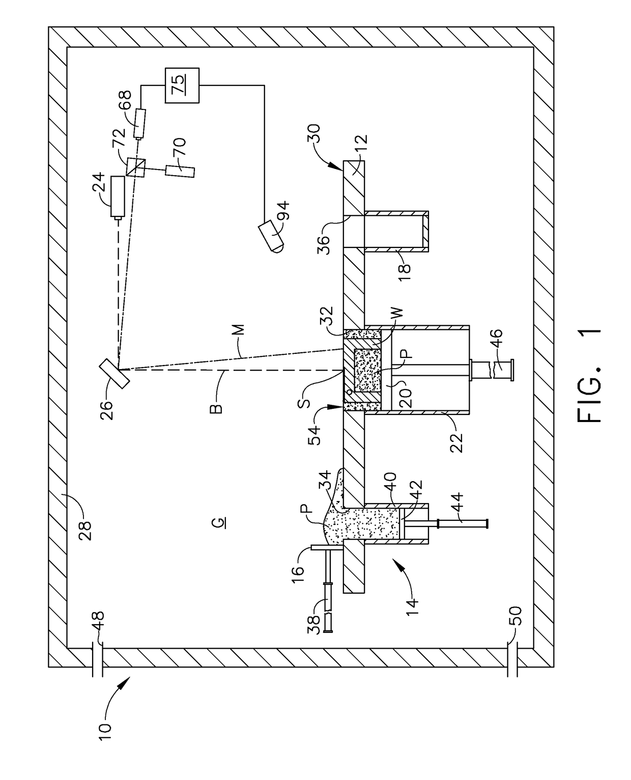
[0015]Referring to the drawings wherein identical reference numerals denote the same elements throughout the various views, FIG. 1 illustrates schematically an apparatus 10 for carrying out an additive manufacturing method. The basic components are a table 12, a powder supply 14, a scraper or recoater 16, an overflow container 18, a build platform 20 surrounded by a build chamber 22, a directed energy source 24, and a beam steering apparatus 26, all surrounded by an enclosure 28. Each of these components will be described in more detail below.

[0016]The table 12 is a rigid structure defining a planar worksurface 30. The worksurface 30 is coplanar with and defines a virtual workplane. In the illustrated example, it includes a build opening 32 communicating with the build chamber 22 and exposing the build platform 20, a supply opening 34 communicating with the powder supply 14, and an overflow opening 36 communicating with the overflow container 18.

[0017]The recoater 16 is a rigid, lat...


PUM

PropertyMeasurementUnit
Massaaaaaaaaaa
Surface propertiesaaaaaaaaaa
Waveaaaaaaaaaa

Abstract

A method for inspecting an additive manufacturing process in which a directed energy source is used to create a weld pool at an exposed build surface of a mass of powdered material, and selectively fuse the powdered material to form a workpiece. The inspection method includes: using a noncontact method to generate an acoustic wave in the build surface; using a noncontact method to measure displacement of the build surface in response to the acoustic wave; and determining at least one sub-surface material property of the workpiece by analyzing the displacement of the build surface.

Description

BACKGROUND OF THE INVENTION[0001]This invention relates generally to additive manufacturing, and more particularly to apparatus and methods for inspection and process control in additive manufacturing.[0002]Additive manufacturing is a process in which material is built up layer-by-layer to form a component. Unlike casting processes, additive manufacturing is limited only by the position resolution of the machine and not limited by requirements for providing draft angles, avoiding overhangs, etc. as required by casting. Additive manufacturing is also referred to by terms such as “layered manufacturing,”“reverse machining,”“direct metal laser melting” (DMLM), and “3-D printing.” Such terms are treated as synonyms for purposes of the present invention.[0003]Prior art additive manufacturing processes typically require a post-build inspection process such as computerized tomography (“CT”) to verify the integrity of the build. While effective, this process requires undesirable extra time ...

Claims


Application Information

Patent Timeline
IPC IPC(8): G01N29/02G01N29/24
CPCG01N2291/267G01N29/2418G01N29/02B33Y50/02B33Y30/00B33Y10/00B22F2999/00G01N29/221B22F10/00B22F10/28B22F12/44B22F10/32B22F12/67B22F10/366B22F12/90B22F10/38B22F10/85B22F10/36B22F2203/03B22F2202/01G01N2291/263B28B1/001G01N29/043G01N29/0672G01N2291/0231B33Y50/00B29C64/153B29C64/393Y02P10/25
Inventor REDDING, MACKENZIE RYANGOLD, SCOTT ALANSPEARS, THOMAS GRAHAM
Owner GENERAL ELECTRIC CO
Why Eureka
Try Eureka