Optical filter and imaging device comprising same

a technology of optical filters and imaging devices, applied in camera filters, television systems, instruments, etc., can solve problems such as image distortion, and achieve the effect of preventing a shift in the transmission spectrum and hindering the transmission in the visible region

Active Publication Date: 2017-05-25
LAH WOO JOO
View PDF3 Cites 37 Cited by
  • Summary
  • Abstract
  • Description
  • Claims
  • Application Information

AI Technical Summary

Benefits of technology

[0012]Such an optical filter can be useful in preventing a shift in a transmission spectrum according to a change in the angle of incidence of light without hindering the transmittance in a visible region.

Problems solved by technology

However, the conventional optical filter has a problem in that the transmission spectrum of the optical filter varies as the angle of incidence of light varies, thereby resulting in distorted images.

Method used


Image

  • Optical filter and imaging device comprising same
  • Optical filter and imaging device comprising same
  • Optical filter and imaging device comprising same

Examples


example 1

Preparative Example 1

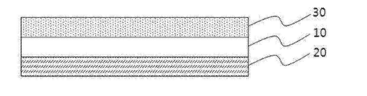
[0080]TiO2 and SiO2 were alternately deposited on one surface of a glass substrate using an E-beam evaporator to form a near-infrared reflection layer.

[0081]Separately, a light absorbent, in which commercially available first and second light absorbents having maximum absorptions of 685 nm and 702 nm, respectively, were mixed at a weight ratio of 1:0.1, a cyclic olefin-based resin as a binder resin source, and toluene (commercially available from Sigma Aldrich) were mixed, and stirred for at least a day using a magnetic stirrer to prepare a solution for near-infrared absorption.

[0082]Next, the prepared solution for near-infrared absorption was spin-coated on the surface of the glass substrate opposite to the surface on which near-infrared reflection layer was formed to form a light absorption layer.

[0083]The optical filter according to one exemplary embodiment of the present invention was manufactured using the above-described method. A stacked structure of the ...

example 2

Preparative Example 2

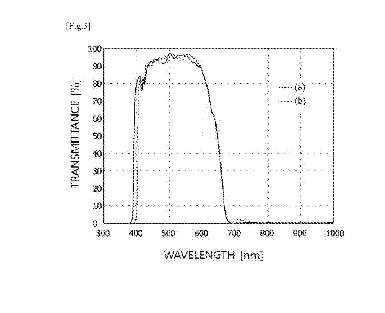
[0085]An optical filter was manufactured in the same manner as in Preparative Example 1, except that a first light absorbent and a second light absorbent were mixed at a weight ratio of 1:0.3 and the resulting mixture was used as the light absorbent included in the light absorption layer.

[0086]A light transmittance test was carried out on the optical filter manufactured in this Preparative Example 2 at different angles of incidence of light of (a) 0° and (b) 30°. The results are shown in FIG. 3.

example 3

Preparative Example 3

[0087]An optical filter was manufactured in the same manner as in Preparative Example 1, except that a first light absorbent and a second light absorbent were mixed at a weight ratio of 1:0.6 and the resulting mixture was used as the light absorbent included in the light absorption layer.

[0088]A light transmittance test was carried out on the optical filter manufactured in this Preparative Example 3 at different angles of incidence of light of (a) 0° and (b) 30°. The results are shown in FIG. 4.


PUM


Abstract

An optical filter and an imaging device comprising the optical filter are provided. The optical filter comprises: a binder resin; a light absorption layer containing at least two kinds of light absorbents dispersed in the binder resin; and a near-infrared reflection layer.

Description

BACKGROUND[0001]Field of the Invention[0002]The present invention relates to an optical filter and an imaging device including the same.[0003]Background Art[0004]Imaging devices such as cameras use a CMOS sensor to convert incident light into electronic signals, thereby forming images. To realize high-quality images with the high pixel counts of the cameras, newly developed back side illuminated-type (BSI-type) CMOS sensors have been applied to main cameras instead of front side illuminated-type (FSI-type) CMOS sensors widely used in the related art. The FSI-type CMOS sensors have an effect of blocking out some of light since wirings are formed on a top surface of a photodiode (PD). On the other hand, the BSI-type CMOS sensors may receive a larger amount of incident light, compared to the FSI-type CMOS sensors, since the wirings are disposed under the photodiode to receive a larger amount of light, and thus have an effect of increasing the intensity of an image by 70% or more. There...

Claims


Application Information

Patent Timeline
Patent Type & Authority Applications(United States)
IPC IPC(8): G02B5/20H04N5/374G02B5/22
CPCG02B5/208H04N5/374G02B5/223G03B11/00H04N25/76G02B5/20
Inventor LAH, WOO JOO
Owner LAH WOO JOO
Why Eureka
Try Eureka