
Fluidized Catalyst Stripping Unit for Displacing Entrained Gas From Catalyst Particles

Active Publication Date: 2017-06-01
DOW GLOBAL TECH LLC
View PDF0 Cites 2 Cited by
  • Summary
  • Abstract
  • Description
  • Claims
  • Application Information

AI Technical Summary

Benefits of technology

The patent describes a fluidized catalyst stripping unit that can remove gas from catalyst particles. The unit includes a two-stage cyclonic separation section, a stripping section with internals, and an inlet for feeding a particulate-fluid suspension from a catalytic reactor. The primary cyclonic separation devices separate most of the particles from the suspension and form a vortex with reduced particulate content. The secondary cyclones discharge the particles into a catalyst bed above the stripping section. The stripping section also has one or more bubble breaking grids located above the stripping section internals and below the catalyst level. The technical effect of this invention is to provide a more efficient and effective means for removing gas from catalyst particles.

Problems solved by technology

In the secondary cyclones, this is believed to occur due to the low solids loading and low dipleg pressure drop which allows gas to flow up the dipleg and cause the secondary cyclone to not be effective at removing particles.
Another potential operational problem is that gas bypassing can occur in a fluidized bed of catalyst due to bubble formation in unconstrained fluidized beds operating at low pressure which causes inefficient catalyst stripping.
This poor catalyst stripping results in valuable product being transported to the combustor and combusted.

Method used


Image

  • Fluidized Catalyst Stripping Unit for Displacing Entrained Gas From Catalyst Particles
  • Fluidized Catalyst Stripping Unit for Displacing Entrained Gas From Catalyst Particles
  • Fluidized Catalyst Stripping Unit for Displacing Entrained Gas From Catalyst Particles

Examples


Embodiment Construction

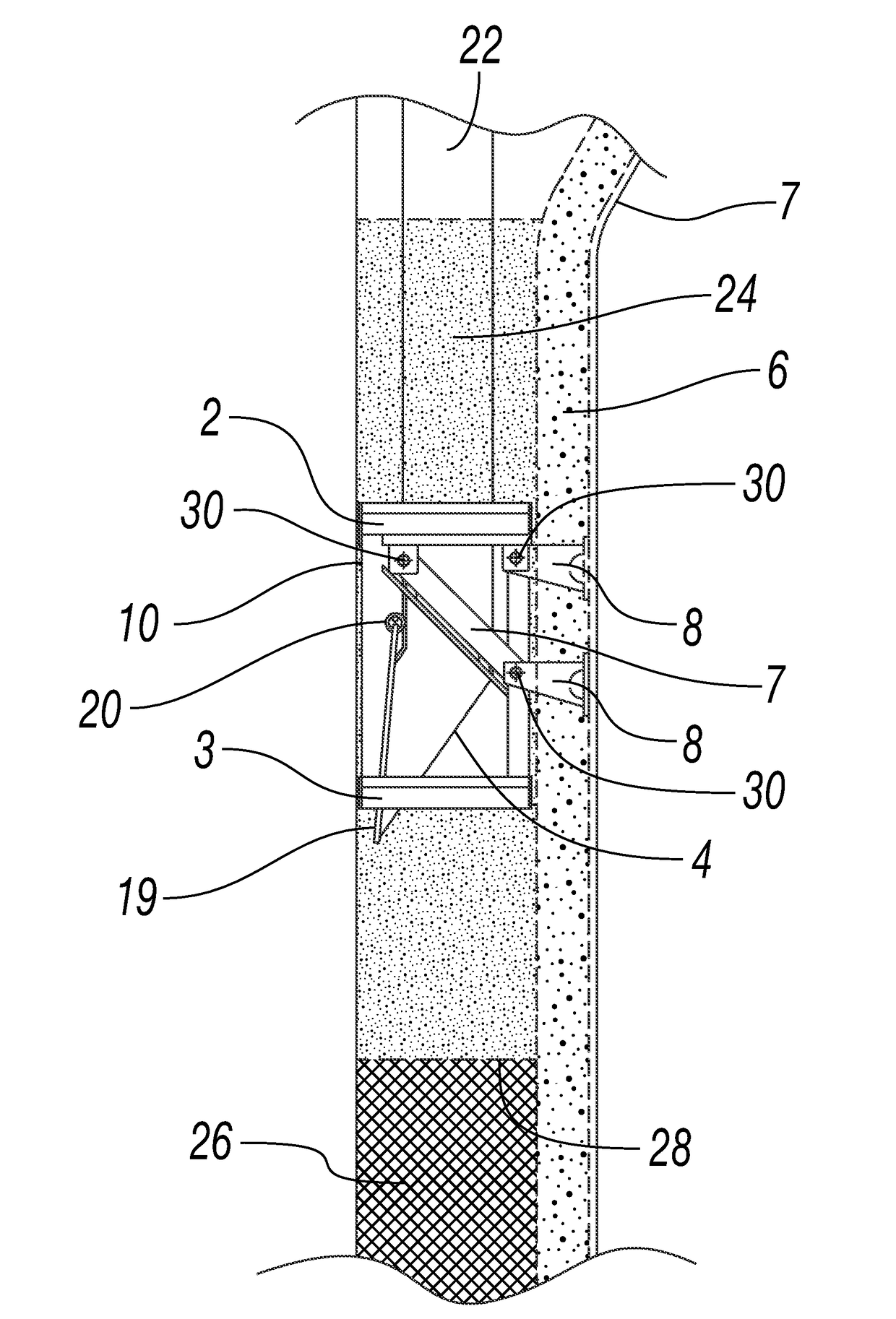
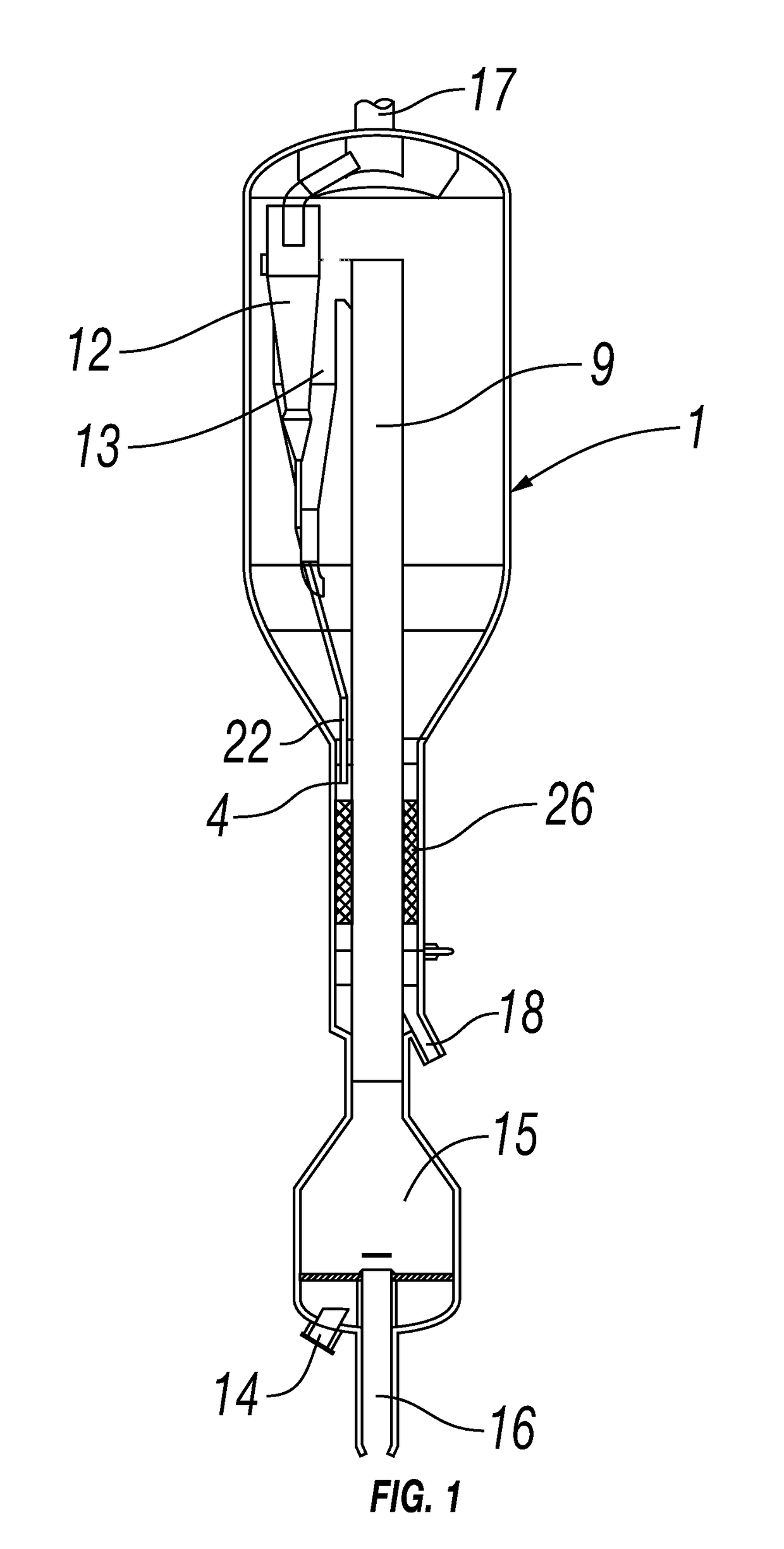
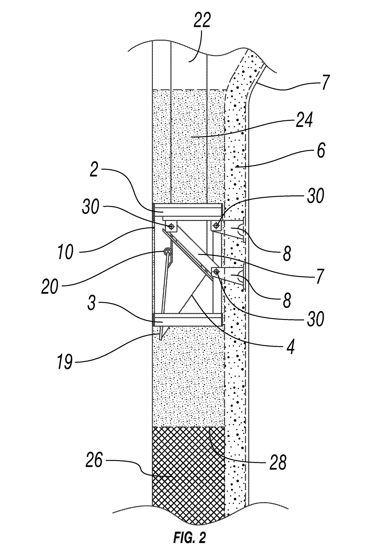
[0008]Referring to FIG. 1, the inventive fluidized catalyst stripping unit for displacing entrained gas from catalyst particles according to embodiments disclosed herein comprises a vessel 1 having a two-stage cyclonic separation section which includes a primary cyclone 13 and a secondary cyclone 12. Vessel 1 further includes an inlet 9 to feed a particulate-fluid suspension to the two stage cyclonic separation section. Each of the primary and secondary cyclones, 13 and 12, respectively, have an internal cylindrical surface (not shown) which acts to separate a major fraction of the catalyst particulates from the suspension and to form a vortex of reduced particulate content. The secondary cyclone 12 has a secondary cyclone dipleg 22 which ends in a particulate discharge outlet 4. The particulate discharge outlet 4 of the secondary cyclone 12 is submerged in a catalyst bed 24 (shown as small dot shading in FIG. 2). Vessel 1 further includes a product outlet 17, a reactant inlet 14, c...


PUM


Abstract

A fluidized catalyst stripping unit for displacing entrained gas from catalyst particles comprising: a vessel housing a two stage cyclonic separation section which comprises one or more primary cyclonic separation devices and one or more secondary cyclones; a stripping section which comprises internals; and an inlet in fluid communication with a catalytic reactor to feed a particulate-fluid suspension to the two stage cyclonic separation section; wherein each primary cyclonic separation device comprises an internal cylindrical surface to separate a major fraction of the particulates from the suspension and form a vortex of reduced particulate content; a particulate discharge outlet from each secondary cyclone to the stripping section; wherein the particulate discharge outlet of the secondary cyclone is submerged in a catalyst bed located above the stripper internals, and wherein the stripping section comprises one or more bubble breaking grids within the catalyst bed and above the stripping internals is provided.

Description

FIELD OF INVENTION[0001]The disclosure relates to a fluidized catalyst stripping unit for displacing entrained gas from catalyst particles.BACKGROUND OF THE INVENTION[0002]In catalytic alkane or alkyl aromatic dehydrogenation processes, reactor secondary cyclone dipleg bypassing and stripper bypassing may occur. In the secondary cyclones, this is believed to occur due to the low solids loading and low dipleg pressure drop which allows gas to flow up the dipleg and cause the secondary cyclone to not be effective at removing particles. Another potential operational problem is that gas bypassing can occur in a fluidized bed of catalyst due to bubble formation in unconstrained fluidized beds operating at low pressure which causes inefficient catalyst stripping. This poor catalyst stripping results in valuable product being transported to the combustor and combusted.SUMMARY OF THE INVENTION[0003]In one embodiment, the disclosure provides a fluidized catalyst stripping unit for displacing...

Claims


Application Information

Patent Timeline
IPC IPC(8): B01J8/34
CPCB01J2208/00991B01J8/34B01J8/0055C07C5/333C10G11/08B01J8/125B01J8/1827B01J8/1872Y02P20/52C07C11/06
Inventor PRETZ, MATTHEW T.
Owner DOW GLOBAL TECH LLC
Learn More