Brake Pad of a Disc Brake
- Summary
- Abstract
- Description
- Claims
- Application Information
AI Technical Summary
Benefits of technology
Problems solved by technology
Method used
Image
Examples
Example
DETAILED DESCRIPTION OF THE DRAWING
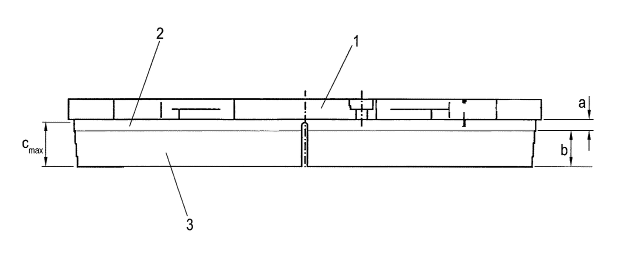
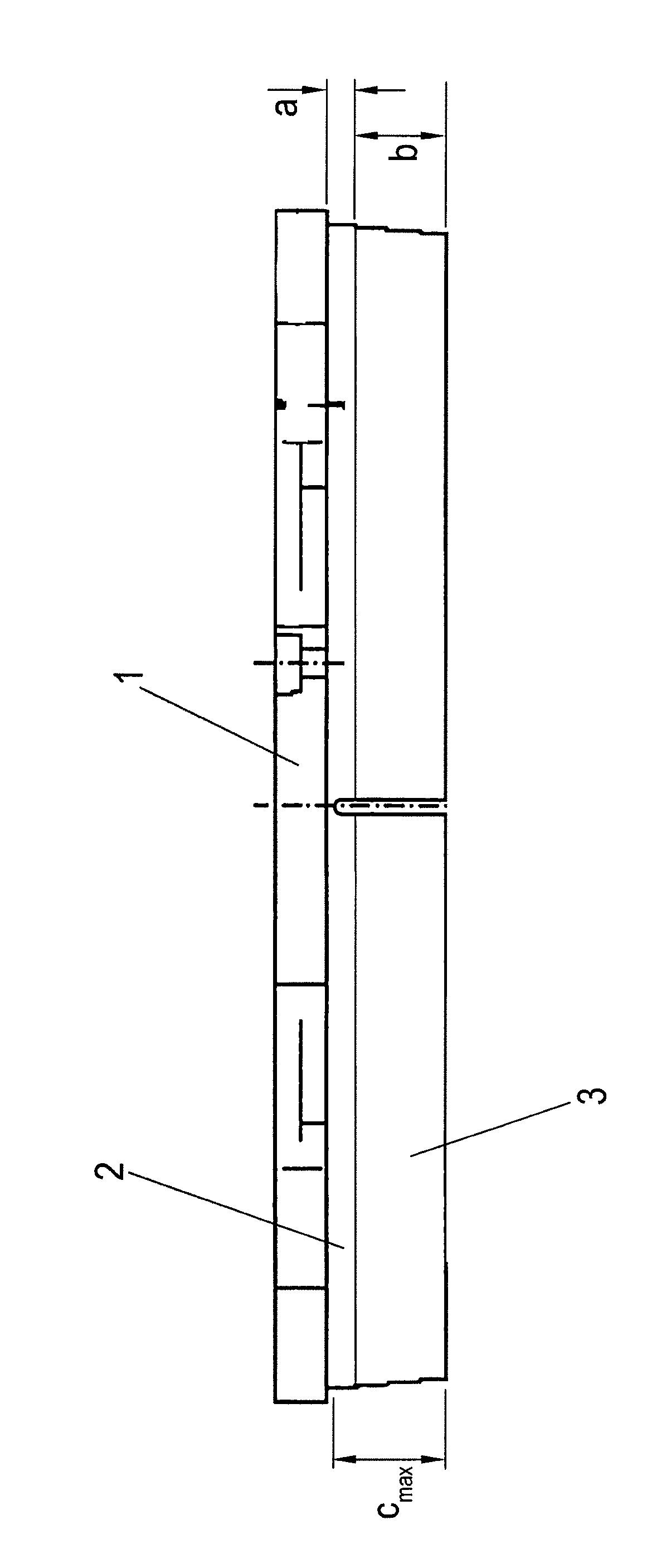
[0021]Represented in the FIGURE is a brake pad of a disc brake, with a pad carrier plate 1, which consists of metal or some other suitable material and may, for example, be formed from cast iron or metal sheet.
[0022]Fastened to the pad carrier plate 1, usually by adhesive bonding and / or interlocking engagement, is an intermediate layer 2, which carries an abrasive friction lining 3, which when in use, that is to say during braking, is in contact under applied pressure with a brake disc on the vehicle. In this case, the friction lining 3 is preferably connected to the intermediate layer by material bonding.
[0023]The brake pad shown is, as it were, a new product, i.e. the friction lining 3 is unused and is at its maximum thickness b. The thickness of the intermediate layer 2 is denoted by a.
[0024]According to the invention, the thickness b of the unused (new) friction lining 3 is smaller than a prescribed maximum wear limit cmax. The thickness b of t...
PUM
 Abstract
Description
Claims
Application Information
 - R&D
- Intellectual Property
- Life Sciences
- Materials
- Tech Scout
- Unparalleled Data Quality
- Higher Quality Content
- 60% Fewer Hallucinations
Browse by: Latest US Patents, China's latest patents, Technical Efficacy Thesaurus, Application Domain, Technology Topic, Popular Technical Reports.
© 2025 PatSnap. All rights reserved.Legal|Privacy policy|Modern Slavery Act Transparency Statement|Sitemap|About US| Contact US: help@patsnap.com


