Electrical connector with elastomeric element and restrainer member to offset relaxation of the elastomer

Inactive Publication Date: 2005-04-28
IBM CORP
View PDF9 Cites 0 Cited by
  • Summary
  • Abstract
  • Description
  • Claims
  • Application Information

AI Technical Summary

Benefits of technology

[0009] A related object is to improve the reliability of a connector which employs a compression mat to force contact members against contact pads.
[0010] A further object is to provi

Problems solved by technology

One disadvantage of this class of connector is that at least one of the first and second mechanical supports must typically be mounted on a housing or other structure, and the contacts must be soldered to conductors.
Connectors of this latter type have a drawback in that the elastomer material of the compression mat has a tendency to relax after the clamping arrangement has been tightened to a desired state.
The relaxation of the material reduces the pressure forcing the contact members against the connector pads, and thus may lead to faulty connections.
However, as the hardness of a compression mat increases, so does the actuation load that is required to compress the

Method used


Image

  • Electrical connector with elastomeric element and restrainer member to offset relaxation of the elastomer
  • Electrical connector with elastomeric element and restrainer member to offset relaxation of the elastomer
  • Electrical connector with elastomeric element and restrainer member to offset relaxation of the elastomer

Examples


Example

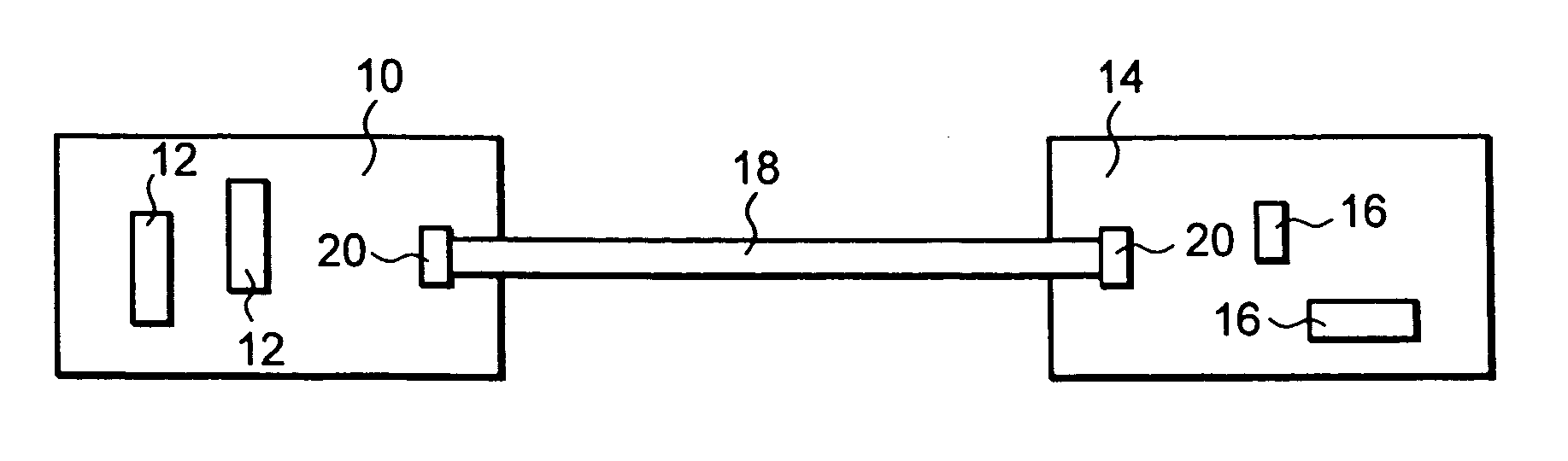
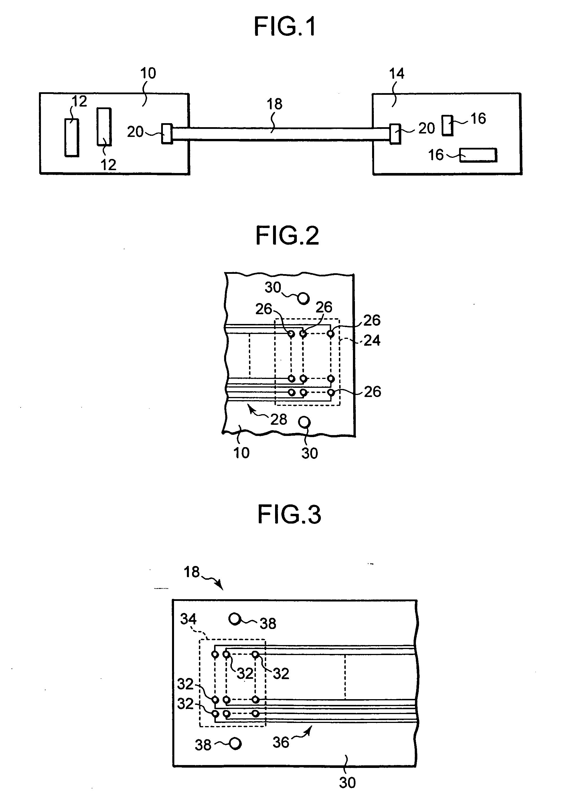
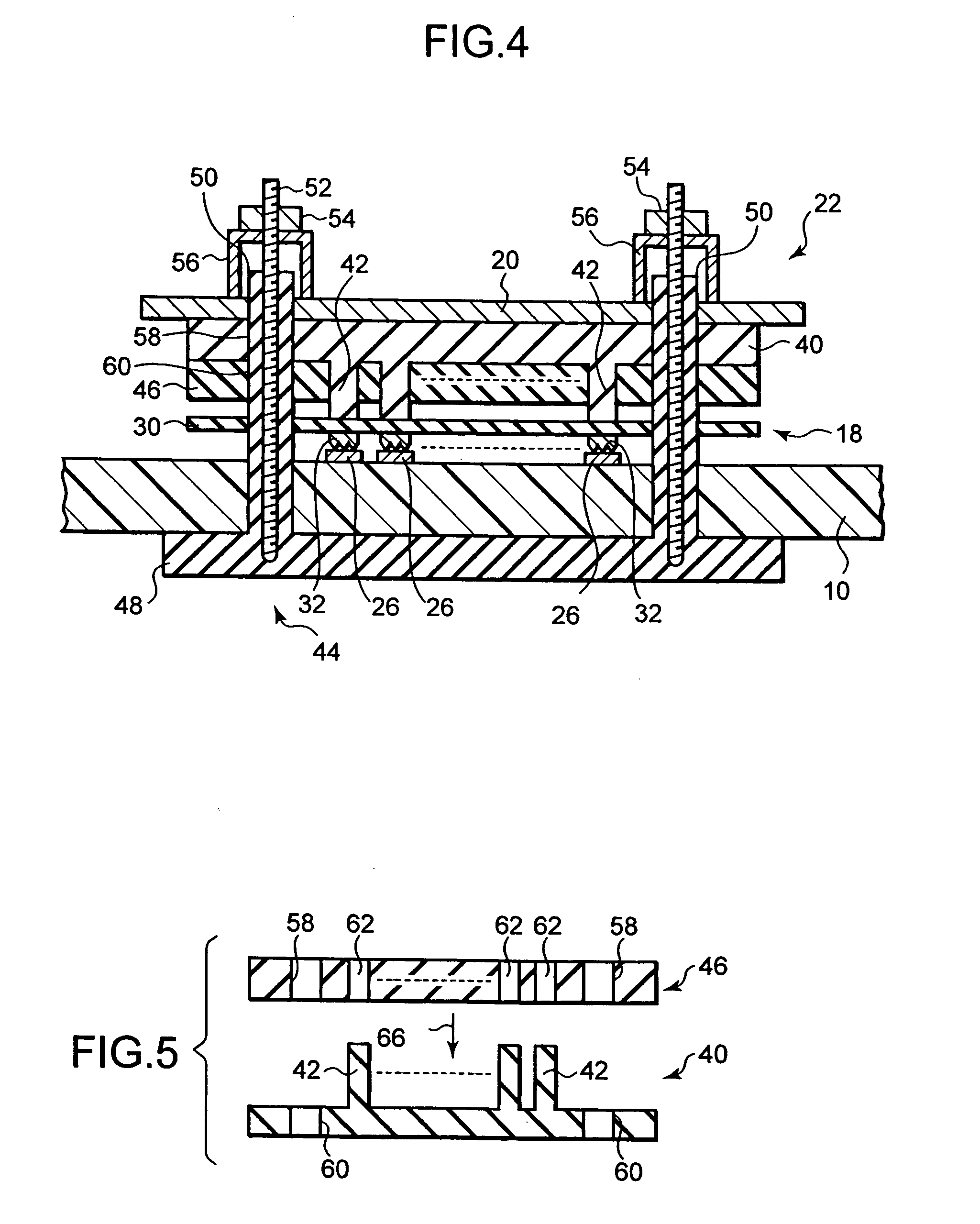
[0018] The present invention is directed to an improved connector that can be used, for example, to connect a ribbon cable to contact pads on an integrated circuit board. FIG. 1 illustrates a first printed circuit board 10 having circuitry such as integrated circuits 12 and a second printed circuit board 14 having circuitry such as integrated circuits 16. A ribbon cable 18 having a plurality of parallel conductors (not shown in FIG. 1) carries signals between the circuitry of the first and second printed circuit boards 10 and 14. Reference number 20 designates a clamping plate that is part of a connector 22 (see FIG. 4) that connects the left end of cable 18 to the circuitry on printed circuit board 10. Similarly, the right end of cable 18 is connected to the circuitry on printed circuit board 14 by a connector 22 that includes a clamping plate 20.

[0019]FIG. 2 illustrates a contact region 24 on the top side of printed circuit board 10. The region 24 contains an array of contact pad...


PUM


Abstract

An electrical connector includes contact pads on a printed circuit board and contact members on a substrate. The contact members are pressed against the contact pads by a compression mat having compressor fingers. A clamping arrangement forces the compressor fingers against the substrate and thereby presses the contact members against the connector pads. The compression mat is made of elastomeric material, which has a tendency to relax and thus reduce the pressure after the clamping arrangement is tightened. A restrainer member is used to offset this tendency of the polymer to relax. The restrainer member has holes through which the compressor fingers of the compression mat extend.

Description

BACKGROUND OF THE INVENTION [0001] The present invention is directed to an electrical connector for use with printed circuit boards. More particularly, the invention is directed to a connector of the type that uses a compression mat made out of elastomer material in order to press contact members against contact pads. [0002] Connectors are in widespread use in the electronics industry. One class of electrical connectors employs a first mechanical support that holds first contacts and a second mechanical support that holds second contacts. In use, the first and second contacts are either pressed against one another or inserted one inside the other. One disadvantage of this class of connector is that at least one of the first and second mechanical supports must typically be mounted on a housing or other structure, and the contacts must be soldered to conductors. [0003] In another class of connectors, printed circuit wiring extends to the edge of a printed circuit board. The edge of th...

Claims


Application Information

Patent Timeline
IPC IPC(8): H01R12/24H01R12/62H05K3/36
CPCH01R12/62H01R12/79H05K3/365
Inventor KUCZYNSKI, JOSEPHTOFIL, TIMOTHY JEROMEVERMILYEA, PAUL ALAN
Owner IBM CORP
Why Eureka
Try Eureka