

Injection mixer
- Summary
- Abstract
- Description
- Claims
- Application Information
AI Technical Summary
Benefits of technology
Problems solved by technology
Method used
Image

Examples
first embodiment
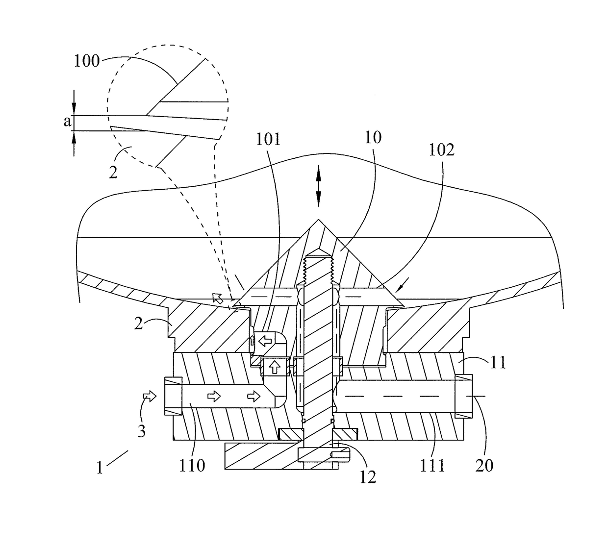
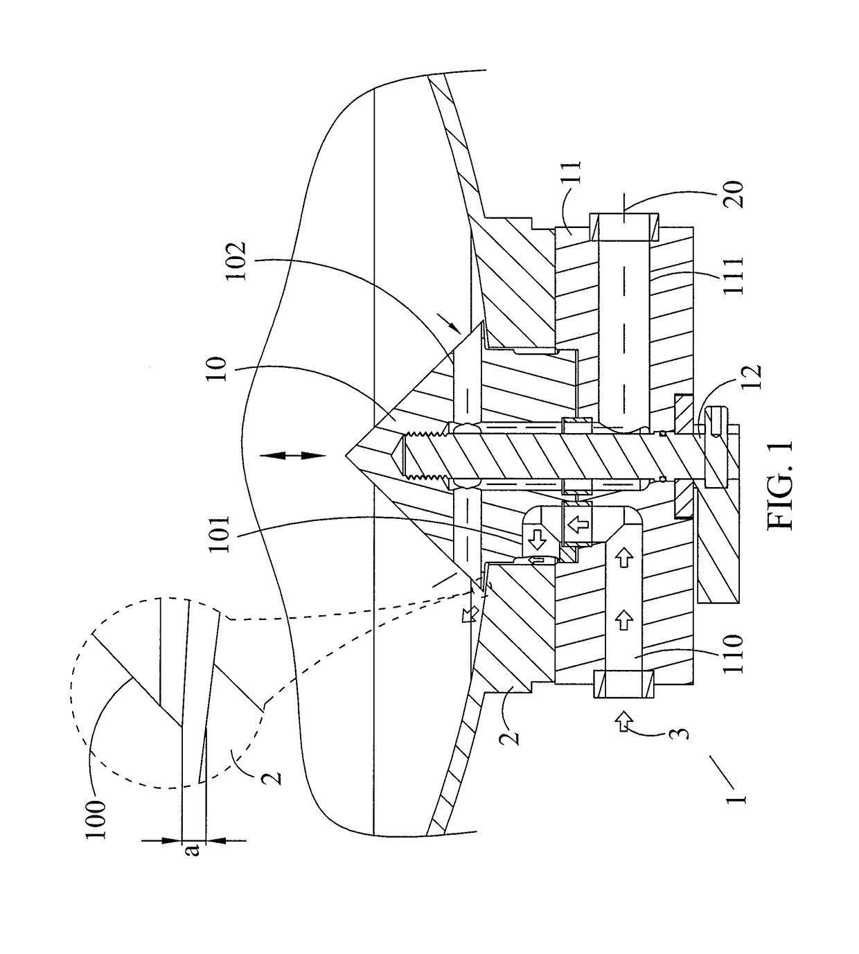
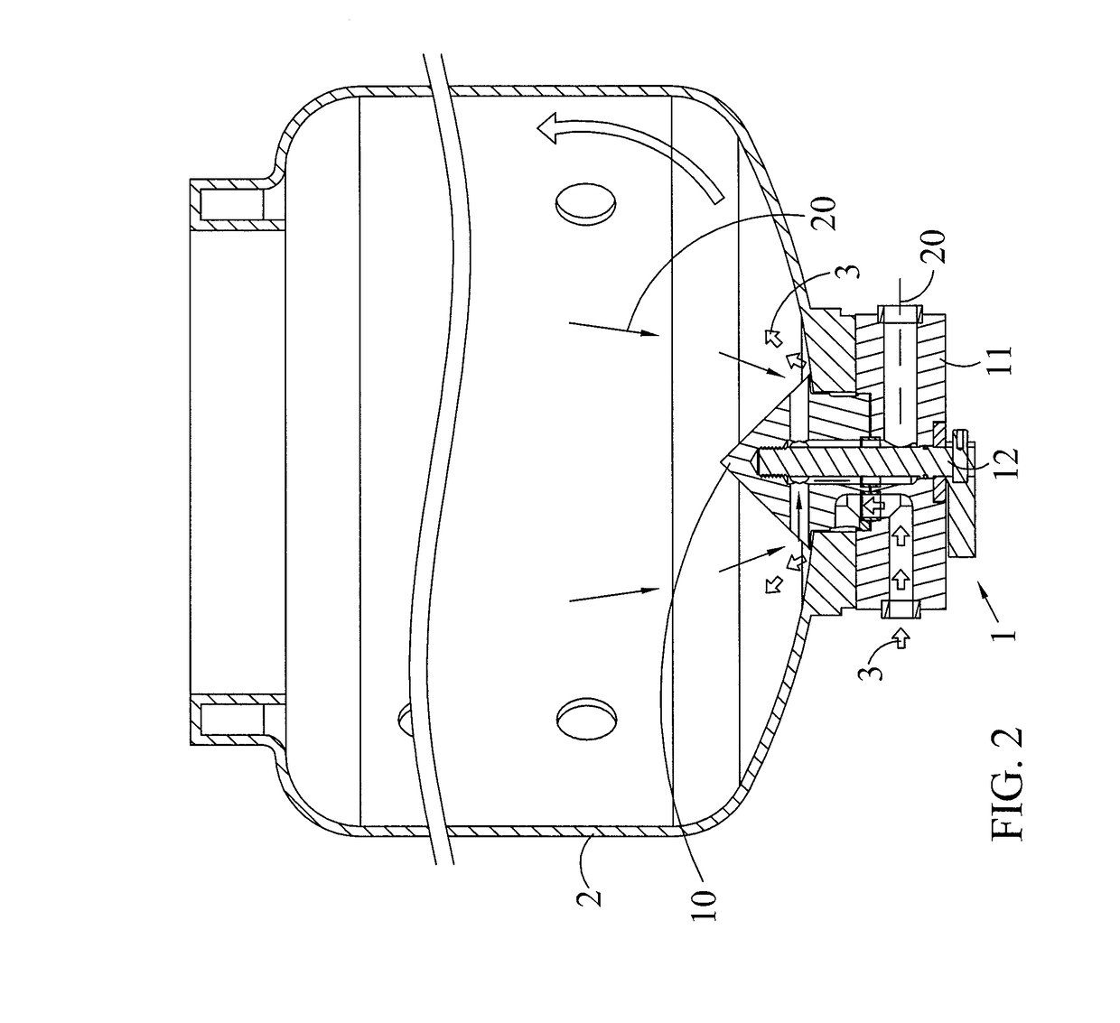
[0030]Referring to FIGS. 1 and 2, which are the first and second schematic diagrams for the first embodiment according to the injection mixer of the present disclosure. As shown in the diagram, the injection mixer 1 may include an injection module 10, a valve seat module 11, and an adjusting module 12. The injection module 10 may be disposed to penetrate one end of a bucket container 2. The edge of the injection module 10 may protrude outwards to form an annular protrusion 100, and the annular protrusion 100 may be separated from the inner wall of the bucket container 2 by a predetermined gap a. The injection module 10 may be disposed with at least one injection channel 101 and at least one fluid intake channel 102. The at least one injection channel 101 may connect one side of the injection module 10 and one end of the injection module 10, and the at least one fluid intake channel 102 may connect the other end of the injection module 10 and the end of the injection module 10. The v...
second embodiment
[0036]The description below makes reference to FIG. 3, which is the schematic diagram for the second embodiment according to the injection mixer of the present disclosure. In the drawing, those components in the injection mixer of the present embodiment functioning in similar fashion as those of the previous embodiment are designated with similar labels, and hence their descriptions are omitted. However, it is worth noting that, in the present embodiment, the injection mixer 1 may further include a fixing module 13, which may be located between one end of the bucket container 2 and one end of the valve seat module 11. The fixing module 13 may surround the injection module 10 and may be detachably connected to the bucket container 2 and the valve seat module 11. Moreover, the fixing module 13 may be a circular structure. The inner wall of the fixing module 13 and the sidewall of the injection module 10 may be separated by a predetermined distance b.
[0037]For example, in the case that...
third embodiment
[0043]The description below makes reference to FIG. 4, which is the schematic diagram for the third embodiment according to the injection mixer of the present disclosure, and FIGS. 1-3 should be incorporated into the reference as well. In the drawing, those components in the injection mixer of the present embodiment functioning in similar fashion as those of the previous embodiment are designated with similar labels, and hence their descriptions are omitted. It is worth noting that, in the present embodiment, the at least one injection channel 101 may be disposed with a fluid intake opening 101a and a fluid discharge opening 101b. The fluid intake opening 101a may be located at one end of the injection module 10, and the fluid discharge opening 101b may be located at one side of the injection module 10. In a preferred embodiment, the fluid supply channel 110 may be disposed with a fluid supply opening 110a and a fluid transporting opening 110b. The fluid supply opening 110a may be d...
PUM
 Abstract
Description
Claims
Application Information