
Manufacturing apparatus for metal molded body

Inactive Publication Date: 2018-02-01
AIDA ENG LTD
View PDF2 Cites 3 Cited by
  • Summary
  • Abstract
  • Description
  • Claims
  • Application Information

AI Technical Summary

Benefits of technology

The present invention is related to a manufacturing apparatus for producing metal molded bodies. The technical effects of the invention include the creation of a partial circulation flow of molten metal in the die through the use of traveling magnetic fields, which promotes better stirring and reduced running on the wall surface. A control circuit can also be used to switch the directions of the thrust units' magnetic fields, which allows for greater efficiency in stirring and flow rate selection based on the type of metal being molded. Additionally, a thrust unit that causes an obliquely vertical traveling magnetic field can be used to create a more laminar flow and fine crystal grains in the metal molded body.

Problems solved by technology

In the cylindrical rabble furnace, the volume of the furnace becomes huge, and huge excitation force is required, which is irrational.

Method used


Image

  • Manufacturing apparatus for metal molded body
  • Manufacturing apparatus for metal molded body
  • Manufacturing apparatus for metal molded body

Examples


Embodiment Construction

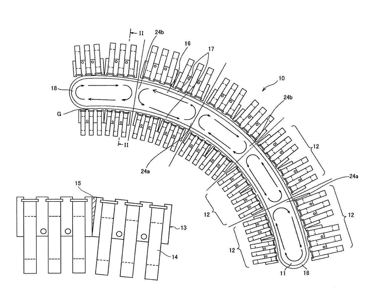
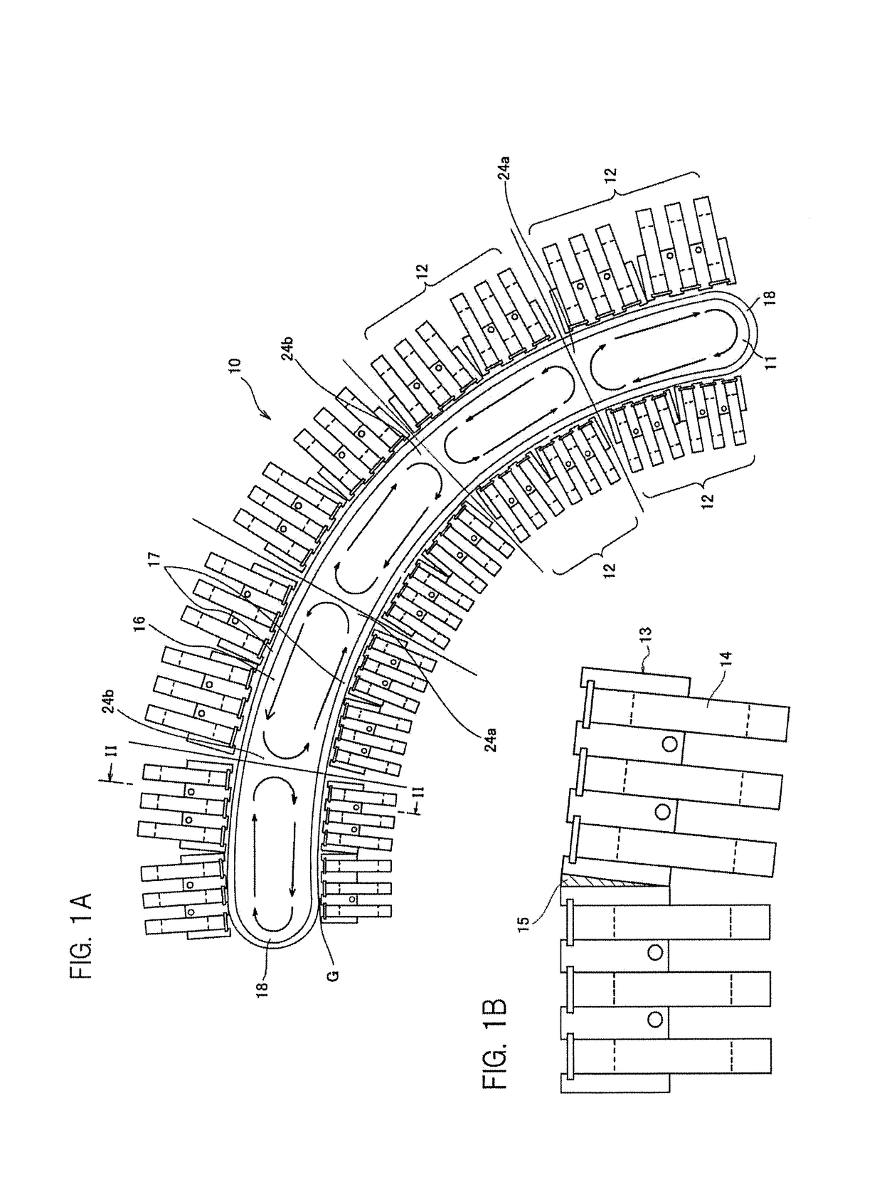
[0022]A manufacturing apparatus (electromagnetic stirring apparatus) 10 for a metal molded body illustrated in FIG. 1A includes an elongated die 11 that is curved in an arc shape in plan view, and a plurality of pairs of thrust units 12 that are disposed along a wall surface of the die with the die disposed therebetween. Each thrust unit 12 includes cores 13, and coils 14 that are wound around the cores 13, as illustrated in FIG. 1B. In this embodiment, two sets each obtained by winding the three coils 14 around the one core 13 are connected through a wedge shaped magnetic body 15 for curvature adjustment at an angle, and are made to be one unit. In FIG. 1A, the wedge shaped magnetic bodies are omitted.

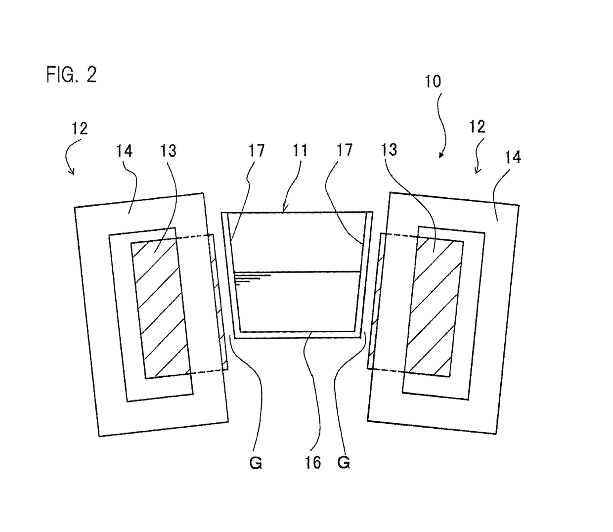
[0023]The die 11 has a substantially U-shaped cross-section including a bottom plate 16, and side walls 17 rising from both ends of the bottom plate, as illustrated in FIG. 2, for example. In general, the depth of the die 11 is deeper than the width. Additionally, the side walls 17 ar...


PUM

PropertyMeasurementUnit
Magnetic fieldaaaaaaaaaa

Abstract

There is provided a manufacturing apparatus for a metal molded body. The manufacturing apparatus includes: a die having an elongated shape in plan view; and a plurality of pairs of thrust units disposed along a wall surface with the die disposed therebetween from both sides of the die, wherein the pairs of thrust units have electromagnetic coils that generate reverse traveling magnetic fields, and the pairs of thrust units arranged in a longitudinal direction are set so as to generate the reverse traveling magnetic fields for each series composed of a single thrust unit or a plurality of the thrust units.

Description

BACKGROUND OF THE INVENTIONField of the Invention[0001]The present invention relates to a manufacturing apparatus for a metal molded body. More specifically, the present invention relates to an apparatus for suppressing growth of a metal crystal by electromagnetically stirring melted metal such as aluminum alloy, cooling the melted metal while discharging residual gas as a source of a mold cavity, and producing a tough metal molded body.Description of Related Art[0002]Description will be made by taking an example of aluminum as metal. In order to produce a precise aluminum material, it is essential that aluminum as a material has a fine crystal structure, and does not have defects such as a mold cavity therein. In order to produce such a material, molten aluminum is transferred to a die of a stirrer (manufacturing apparatus for a metal molded body), and growth of a crystal structure is prevented by stirring and cooling the molten aluminum in the die, so that a dense material is prod...

Claims


Application Information

Patent Timeline
IPC IPC(8): B22D11/115B22D11/16B22D11/00
CPCB22D11/115B22D11/16B22D11/003B22D27/02
Inventor MURAMATSU, MASAHARUSHIBASAKI, SHOGOYAHARA, MASATAKA
Owner AIDA ENG LTD
Learn More