Electrical receptacle connector

a technology of electrical receptacles and connectors, which is applied in the direction of coupling devices, two-part coupling devices, electrical apparatus, etc., can solve the problems of inefficiency of the receptacle terminals of the electrical receptacle connectors with the plug terminals of the electrical plug connectors, and achieve the effect of convenient manufacture and good stability and reliability

Active Publication Date: 2017-06-01
ADVANCED CONNECTEK INC
View PDF24 Cites 0 Cited by
  • Summary
  • Abstract
  • Description
  • Claims
  • Application Information

AI Technical Summary

Benefits of technology

[0016]As above, recesses are provided in the terminal grooves for receiving end portions of the flat contact portions of the first receptacle terminals, and the abutting surfaces of the end portions are abutted against the first lateral surfaces of the recesses. Therefore, when the tongue portion is inserted into or detached from an electrical plug connector, the end portions are constrainted in the recesses. As a result, upon the tongue portion is deflected, the flat contact portions are not detached from the tongue portion. Accordingly, the connector can provide good stability and reliability in the contact with the electrical plug connector.

Problems solved by technology

Hence, in operation, the receptacle terminals of the electrical receptacle connector would not contact the plug terminals of an electrical plug connector efficient

Method used


Image

  • Electrical receptacle connector
  • Electrical receptacle connector
  • Electrical receptacle connector

Examples


Embodiment Construction

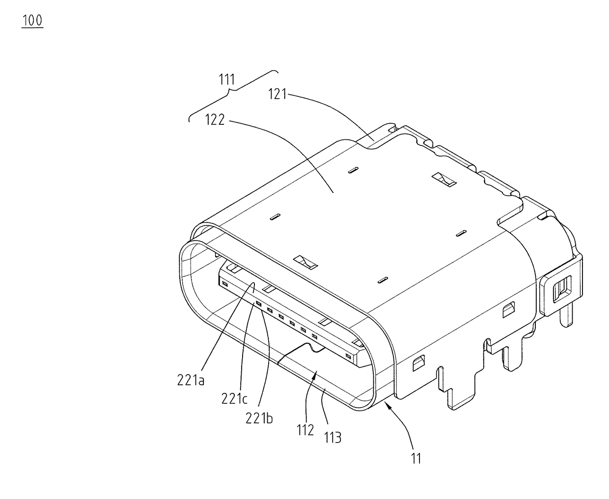
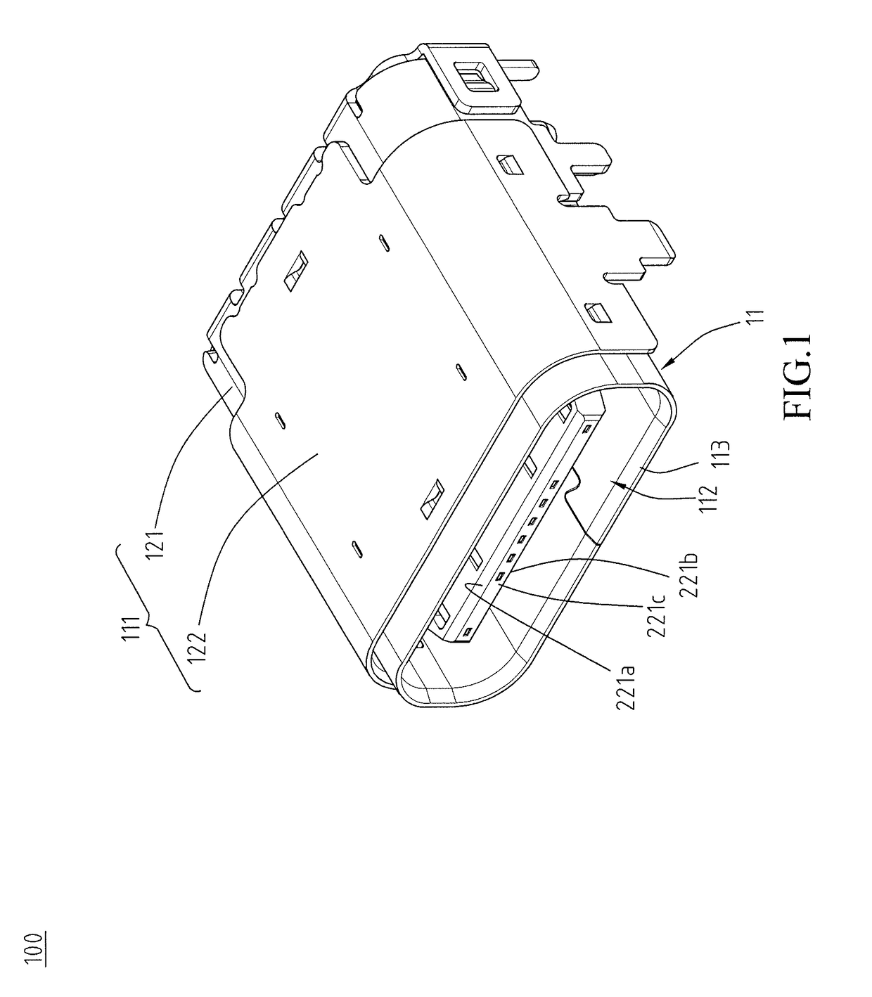
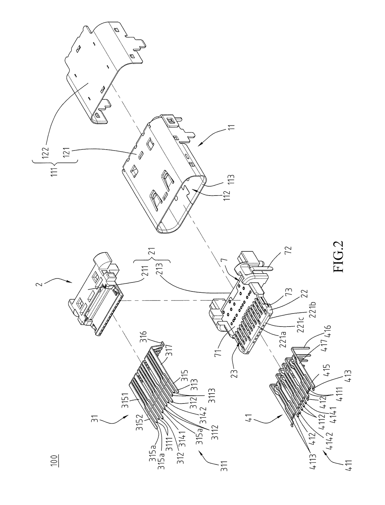
[0028]Please refer to FIGS. 1 and 2, illustrating an electrical receptacle connector of an exemplary embodiment of the instant disclosure. FIG. 1 illustrates a perspective view of an electrical receptacle connector according to an exemplary embodiment of the instant disclosure. FIG. 2 illustrates an exploded view of the electrical receptacle connector. In this embodiment, the electrical receptacle connector 100 is assembled with a circuit board by sinking technique. That is, one side of the circuit board is cut to form a crack, and the electrical receptacle connector 100 is positioned at the crack and extending toward the side portion of the circuit board. In this embodiment, the electrical receptacle connector 100 can provide a reversible or dual orientation USB Type-C connector interface and pin assignments, i.e., a USB Type-C receptacle connector. In this embodiment, the electrical receptacle connector 100 comprises a metallic shell 11, a mount member 21, a tongue portion 22, a p...


PUM


Abstract

An electrical receptacle connector includes a mount member, a tongue, first terminals, second terminals, and a shielding plate. The mount member and the tongue are received in a metallic shell. The terminals and the shielding plate are on the mount member and the tongue. The tongue includes terminal grooves and recesses. The terminal grooves are formed on a first surface of the tongue. Each of the recesses is recessed toward a tip of the tongue from an inner sidewall in the corresponding terminal groove. Flat contact portions of the first terminals are held in the terminal grooves. End portions of the flat contact portions are received in the recesses. Therefore, upon the tongue is deflected, the flat contact portions are constrainted in the recesses and not detached from the tongue, thereby improving stability and reliability in the contact with an electrical plug connector.

Description

CROSS-REFERENCE TO RELATED APPLICATION[0001]This non-provisional application claims priority under 35 U.S.C. §119(a) to Patent Application No. 201520953468.2 filed in China, P.R.C. on Nov. 26, 2015, the entire contents of which are hereby incorporated by reference.FIELD OF THE INVENTION[0002]The instant disclosure relates to an electrical connector, and more particular to an electrical receptacle connector.BACKGROUND[0003]Generally, Universal Serial Bus (USB) is a serial bus standard to the PC architecture with a focus on computer interface, consumer and productivity applications. The existing Universal Serial Bus (USB) interconnects have the attributes of plug-and-play and ease of use by end users. Now, as technology innovation marches forward, new kinds of devices, media formats and large inexpensive storage are converging. They require significantly more bus bandwidth to maintain the interactive experience that users have come to expect. In addition, the demand of a higher perfor...

Claims


Application Information

Patent Timeline
IPC IPC(8): H01R24/60H01R13/6585H01R13/502
CPCH01R24/60H01R2107/00H01R13/6585H01R13/502
Inventor TSAI, YU-LUNHOU, PIN-YUANLIAO, CHUNG-FUSU, RUICHEN, LONG-FEI
Owner ADVANCED CONNECTEK INC
Why Eureka
Try Eureka