
System and method for predicting patient falls

a patient and system technology, applied in the field of patient monitors, can solve the problems of burdening the staff of healthcare professionals with unnecessary interventions and high cost of round-the-clock patient monitoring by staff nurses

Pending Publication Date: 2017-06-01
CAREVIEW COMM INC
View PDF17 Cites 30 Cited by
  • Summary
  • Abstract
  • Description
  • Claims
  • Application Information

AI Technical Summary

Benefits of technology

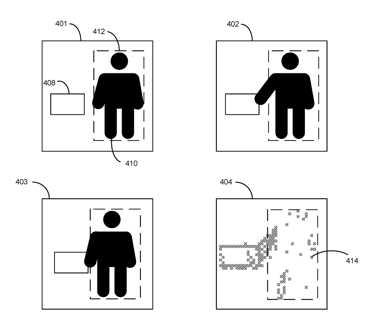
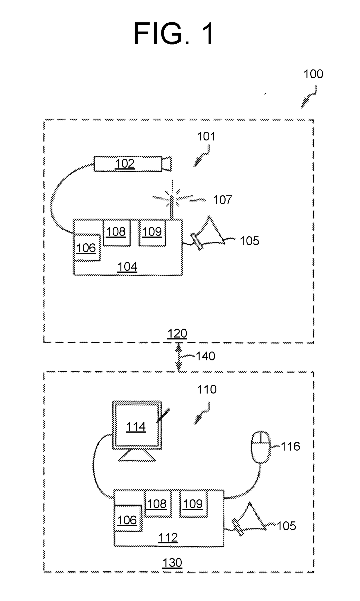
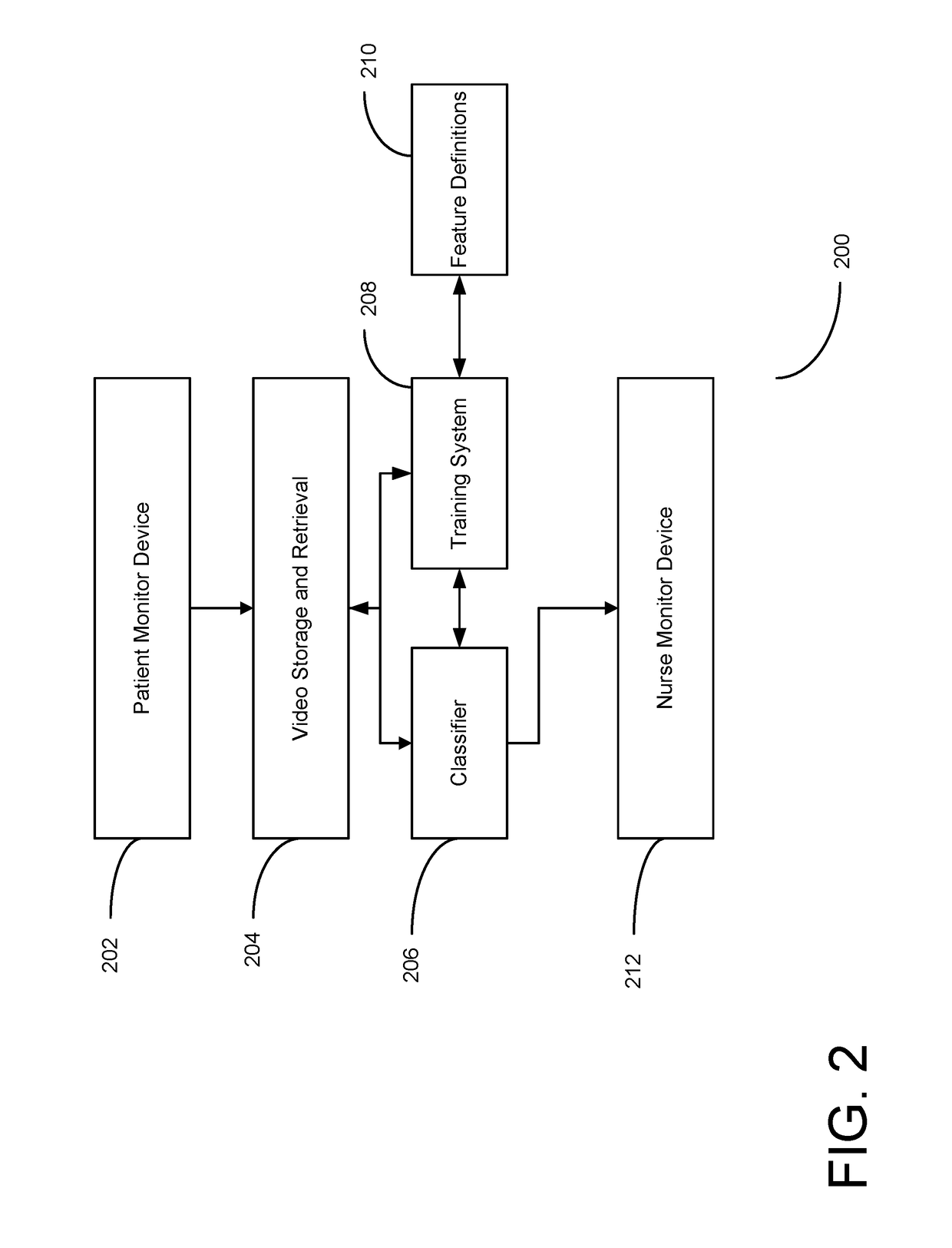
The present invention provides a method and system for detecting a fall risk condition in a patient area using a surveillance camera and computer system. The computer system analyzes frames from the camera and identifies features such as the centroid, centroid area, connected components ratio, bed motion percentage, and unconnected motion. It then generates motion images and a classifier to detect fall risk events based on these features. When a fall risk event is detected, the computer system issues a fall alert with both visual and auditory signals. The technical effect of this invention is to provide a reliable and effective method for identifying and responding to fall risk events in a patient area, which can help to prevent accidents and improve patient safety.

Problems solved by technology

Healthcare facilities invest a huge amount of their resources in falls management programs and assessing the risk of falls in a particular patient class, location, and care state, along with the risk factors associated with significant injuries.
Round the clock patient monitoring by a staff nurse is expensive, therefore, healthcare facilities have investigated alternatives in order to reduce the monitoring staff, while increasing patient safety.
Such automated systems may be susceptible to false alarms, which can burden a staff of healthcare professionals with unnecessary interventions.

Method used


Image

  • System and method for predicting patient falls
  • System and method for predicting patient falls
  • System and method for predicting patient falls

Examples


Embodiment Construction

[0039]In the following description, reference is made to the accompanying drawings that form a part hereof, and in which is shown by way of illustration, specific embodiments in which the invention may be practiced. These embodiments are described in sufficient detail to enable those skilled in the art to practice the invention, and it is to be understood that other embodiments may be utilized. It is also to be understood that structural, procedural and system changes may be made without departing from the spirit and scope of the present invention. The following description is, therefore, not to be taken in a limiting sense. For clarity of exposition, like features shown in the accompanying drawings are indicated with like reference numerals and similar features as shown in alternate embodiments in the drawings are indicated with similar reference numerals.

[0040]As will be appreciated by one of skill in the art, the present invention may be embodied as a method, system, or computer ...


PUM


Abstract

A method and system for detecting a fall risk condition, the system comprising a surveillance camera configured to generate a plurality of frames showing a surveillance viewport of an area including a patient area, and a computer system comprising memory and logic circuitry configured to identify a first set of frames from the plurality of frames, generate motion images for the first set of frames, determine features from the motion images, the features including at least one of a centroid, centroid area, connected components ratio, bed motion percentage, and unconnected motion, train a classifier based on the determined features from the motion images, receive a second set of frames from the plurality of frames, detect a fall risk event associated with the second set of frames using the classifier, and issue a fall alert based on the detection of the fall risk event, the fall alert comprising one or both of a visual indication and an audible indication.

Description

CROSS-REFERENCE TO RELATED APPLICATIONS[0001]This application claims the priority of U.S. Provisional Application No. 62 / 261,810, entitled “SYSTEM AND METHOD FOR PREDICTING PATIENT FALLS,” filed on Dec. 1, 2015, the disclosure of which is hereby incorporated by reference in its entirety.[0002]The present application is related to the following patents and applications, which are assigned to the assignee of the present invention:[0003]U.S. Pat. No. 7,477,285, filed Dec. 12, 2003, entitled “Non-intrusive data transmission network for use in an enterprise facility and method for implementing,”[0004]U.S. Pat. No. 8,471,899, filed Oct. 27, 2009, entitled “System and method for documenting patient procedures,”[0005]U.S. Pat. No. 8,675,059, filed Jul. 29, 2010, entitled “System and method for using a video monitoring system to prevent and manage decubitus ulcers in patients,”[0006]U.S. Pat. No. 8,676,603, filed Jun. 21, 2013, entitled “System and method for documenting patient procedures,”...

Claims


Application Information

Patent Timeline
IPC IPC(8): H04N7/18G06K9/46G06K9/62A61B5/11G06T7/20
CPCH04N7/183A61B5/1117G06K9/4604G06T7/20G06K9/6269A61B5/1128G06V20/52G06F18/2411
Inventor JOHNSON, STEVEN GAILDEL CARPIO, DEREK
Owner CAREVIEW COMM INC
Learn More