Torsional vibration reduction device

Active Publication Date: 2017-06-08
TOYOTA JIDOSHA KK
View PDF13 Cites 2 Cited by
  • Summary
  • Abstract
  • Description
  • Claims
  • Application Information

AI Technical Summary

Benefits of technology

[0017]According to the torsional vibration reduction device of the invention described above, the retaining member is enclosed and fixed inside the housing. That is, the retaining member is not exposed to outside of the housing, so openings and gaps in the housing are able to be directly closed up by, for example, welding together the members that form the housing. As a result, the housing is able to be reliably sealed, and this sealability is able to be improved. Also, because the housing is directly closed up, the number of parts is able to be reduced by that amount. Furthermore, the housing is designed to shield the rolling element from fluid inside the fluid power transmitting device, and is thus configured so as not to contact the rolling element. That is, the housing does not receive a load associated with reciprocating motion of the rolling element, and is thus able to be formed thinner than the retaining member. If this housing is fastened to the driven side member of the fluid power transmitting device by a rivet, the length of the rivet is able to be shorter than it is when the retaining member is fastened to the driven side member by a rivet. As a result, the fastening by the rivet is able to be more reliable, and reliability after fastening is able to be improved. Furthermore, the space of the connecting portion of the driven side member and the housing is able to be reduced.
[0018]Also, with the torsional vibration reduction device of the invention described above, the housing is formed by

Problems solved by technology

However, in this case, if the material of which the rotating body is formed is different from the material of which the case member is formed, weldi

Method used


Image

  • Torsional vibration reduction device
  • Torsional vibration reduction device
  • Torsional vibration reduction device

Examples


Example

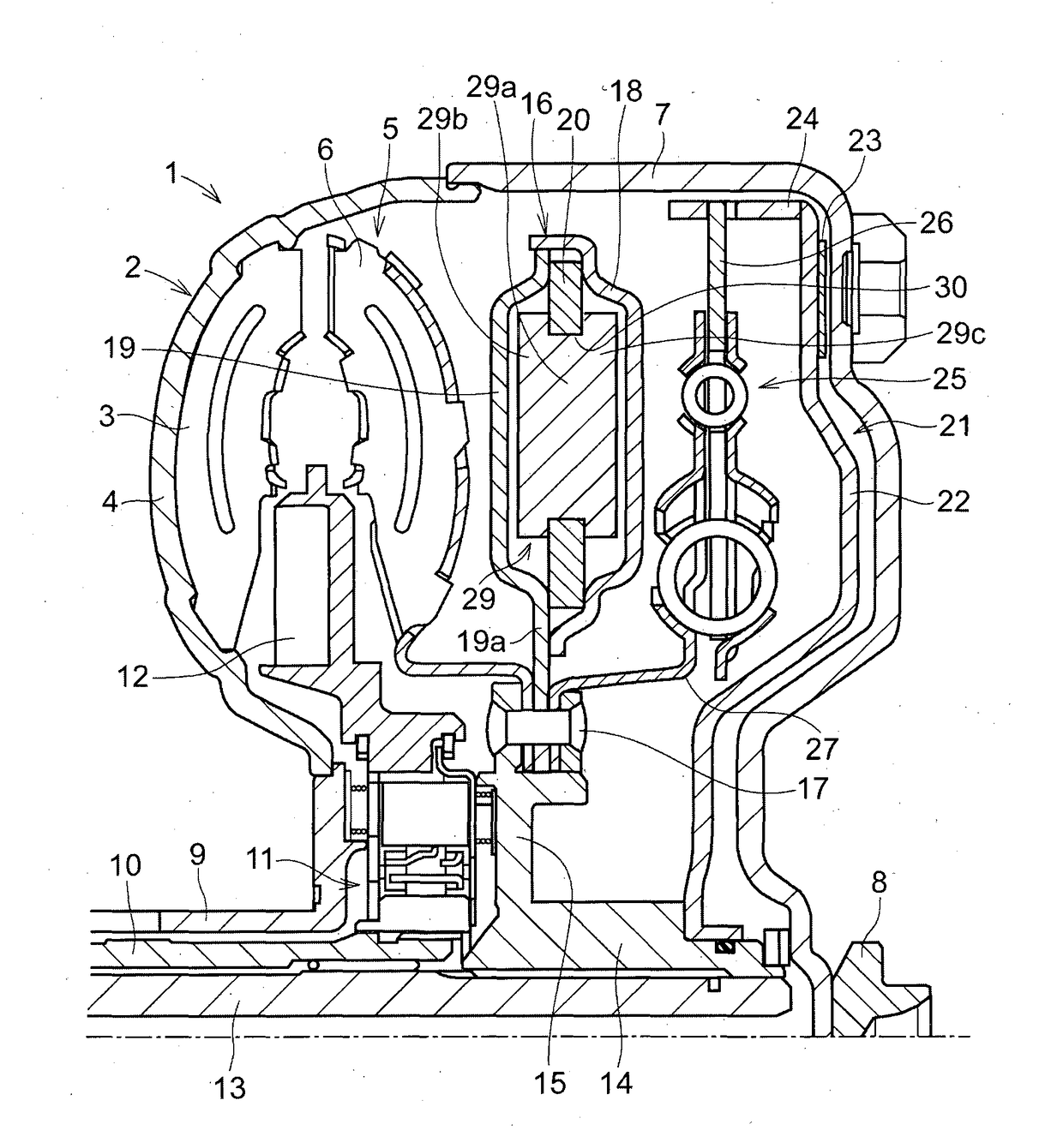
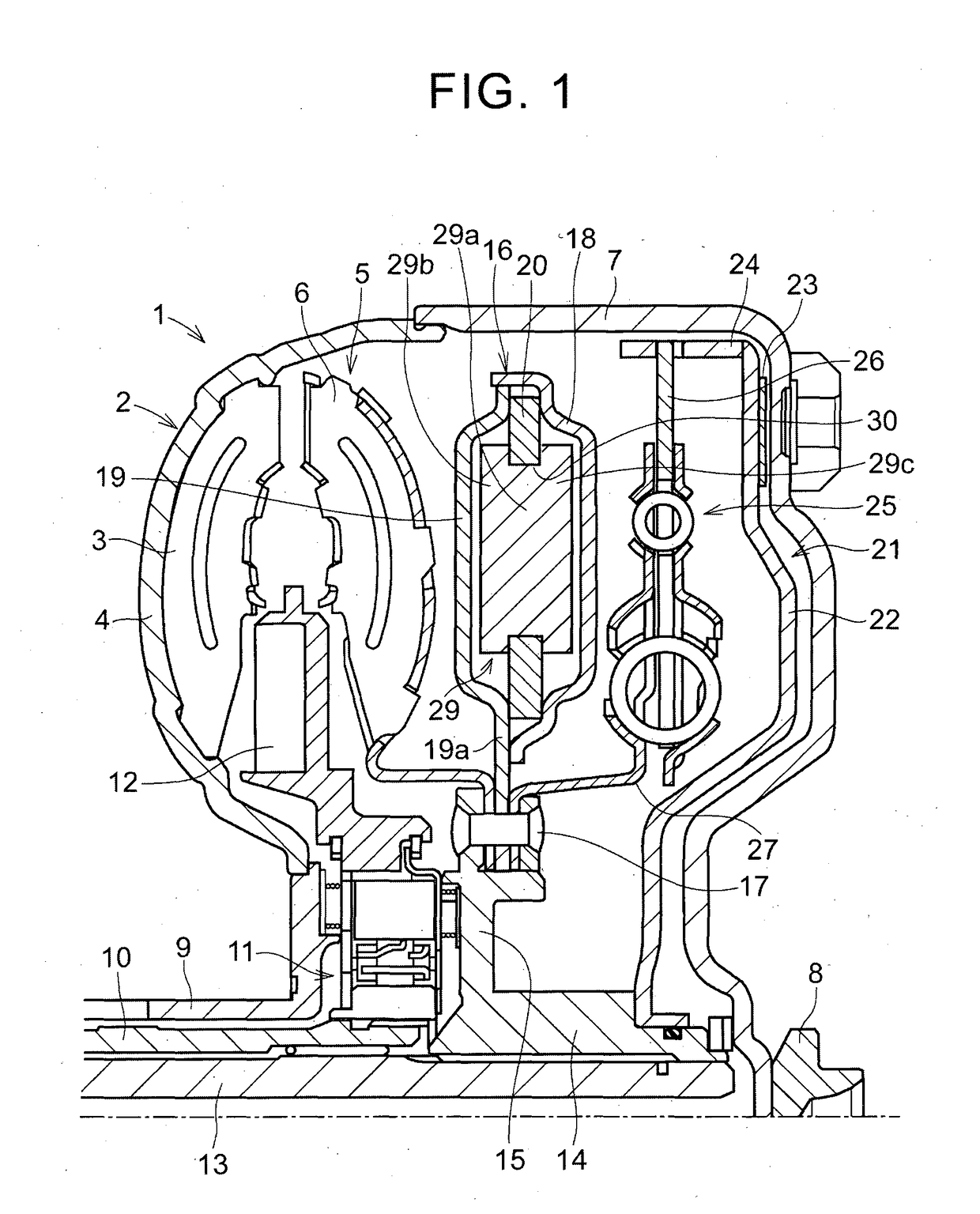
[0031]In order to describe the invention in detail, first, a first example embodiment of the invention will be described. FIG. 1 is a view of an example in which a torsional vibration reduction device according to a first example embodiment of the invention is provided inside of a torque converter that is a fluid power transmitting device for multiplying torque. The basic structure of this torque converter 1 is similar to that of a conventionally-known torque converter. That is, a pump impeller 2 that is a driving side member that generates a fluid flow inside the fluid power transmitting device, and is a member on the input side, is formed having pump blades 3 that are arranged in an annular shape attached to an inside surface of a pump shell 4, and a turbine runner 5 that is arranged facing the pump impeller 2. This turbine runner 5 is driven by the fluid flow and has a shape that is substantially symmetrical with the pump impeller 2. The turbine runner 5 has multiple turbine blad...


PUM


Abstract

A torsional vibration reduction device that is provided inside of a fluid power transmitting device that has a driving side member that generates a fluid flow, and a driven side member that is driven by the fluid flow, includes a rolling element configured to move in a reciprocating manner according to a variation in torque; a retaining member that has a rolling chamber configured to house the rolling element in a manner that enables the rolling element to move in a reciprocating manner; and a housing configured to shield the rolling element and the rolling chamber from fluid inside of the fluid power transmitting device. The retaining member is enclosed and fixed inside the housing, and the housing is fixed to the driven side member.

Description

BACKGROUND OF THE INVENTION[0001]1. Field of the Invention[0002]The invention relates to a device that reduces torsional vibration due to reciprocating motion or pendulum motion of an inertial mass.[0003]2. Description of Related Art[0004]Examples of this kind of device are described in International Publication No. WO 2013 / 161058, International Publication No. WO 2013 / 128590, and Japanese Patent Application Publication No. 2013-44370 (JP 2013-44370 A). In these devices, inertial mass is configured as a rolling element, and this rolling element is housed in a rolling chamber formed in a rotating body. These devices are configured to reduce torsional vibration when it is generated in the rotating body, by the rotating body moving inside the rolling chamber in a reciprocating manner according to the torsional vibration. Each of these devices is arranged inside of a torque converter. With the structures described in International Publication No. WO 2013 / 161058 and International Publica...

Claims


Application Information

Patent Timeline
IPC IPC(8): F16H45/02F16F15/14
CPCF16H45/02F16H2045/0226F16H2045/0263F16F15/145F16H2045/0205F16H2045/0278
Inventor MIYAHARA, YUTSUKANO, FUSAHIROHONDA, ATSUSHI
Owner TOYOTA JIDOSHA KK
Why Eureka
Try Eureka