Vehicular Information Display Apparatus

Inactive Publication Date: 2017-06-08
TOYOTA JIDOSHA KK
View PDF3 Cites 7 Cited by
  • Summary
  • Abstract
  • Description
  • Claims
  • Application Information

AI Technical Summary

Benefits of technology

[0012]In the above aspect, the controller changes the arrangement of information in the vehicle information image. The vehicle information image includes the first region and the second region disposed adjacent to each other in the right-left direction. The first region includes the first image portion representing the current vehicle speed, and the second region includes the second image portion representing the vehicle information different from the vehicle speed information. The first image portion includes the vehicle speed value display representing the vehicle speed value that is an integer value, and the unit display representing the unit of the vehicle speed value. The space required for the vehicle speed value display changes in response to a change in the number of digits of the vehicle speed value. Therefore, the position of the vehicle speed value display is left-aligned in the first region, whereby a space on the right side in the first region can be made wider when the number of digits of the vehicle speed value is one or two. Thus, when the number of digits of the vehicle speed value is one or two, the space in the right-left direction between the vehicle speed value display in the first region and the display of the second image portion in the second region can be made wider. As a result, it is possible to improve the readability of these displays and to reduce obstruction of the driver's view. When the position of the vehicle speed value display is left-aligned in the first region, setting the position of the unit di

Problems solved by technology

From this point of view, the related art as described in JP 2015-141161 A is hard to realize under the condition that the size of a vehicle information image is limited.
In this case, the readability of each image portion may be reduced, or the driver's view through the space may be obs

Method used


Image

  • Vehicular Information Display Apparatus
  • Vehicular Information Display Apparatus
  • Vehicular Information Display Apparatus

Examples


Example

[0029]Hereinafter, an example embodiment of the disclosure will be described with reference to the accompanying drawings.

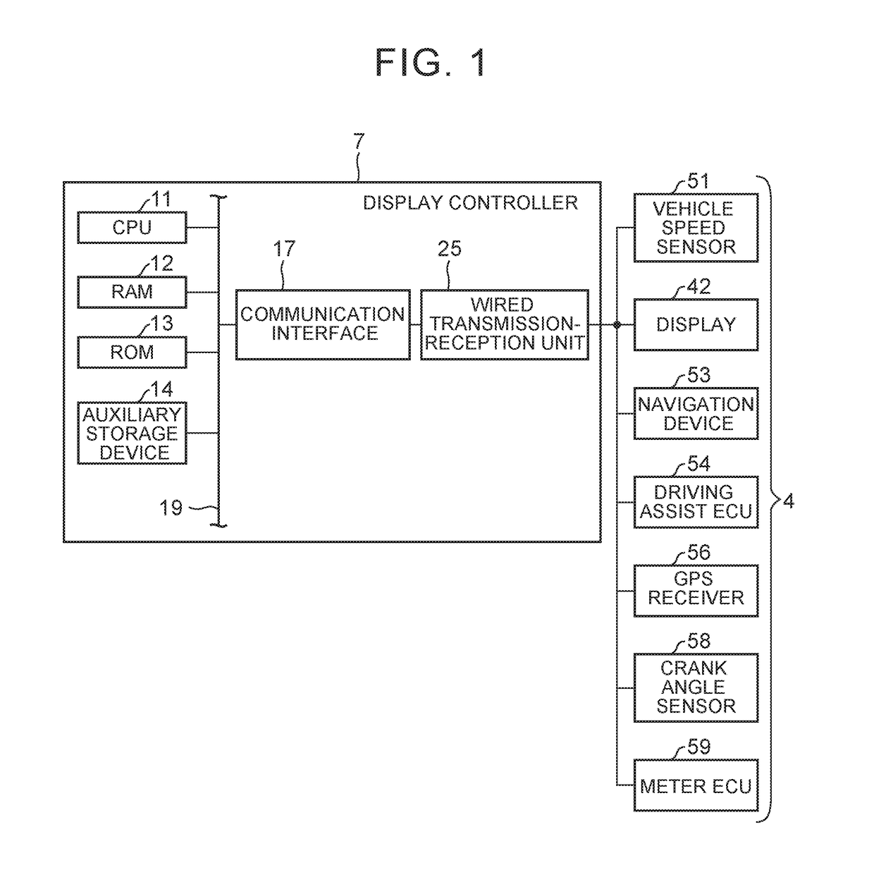
[0030]FIG. 1 is a diagram showing an example of a vehicle system relating to a vehicular information display apparatus. FIG. 1 also shows the hardware configuration of a display controller 7.

[0031]The vehicle system is mounted in a vehicle. The vehicle is a right-hand drive vehicle. The vehicle system includes an in-vehicle electronic device group 4 and the display controller 7.

[0032]The in-vehicle electronic device group 4 includes, for example, a display device (projector) 42, a vehicle speed sensor 51, a navigation device 53, a driving assist electronic control unit (ECU) 54, a global positioning system (GPS) receiver 56, a crank angle sensor 58, and a meter electronic control unit (ECU) 59.

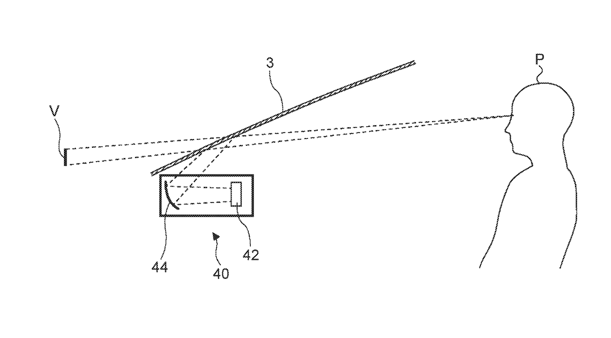
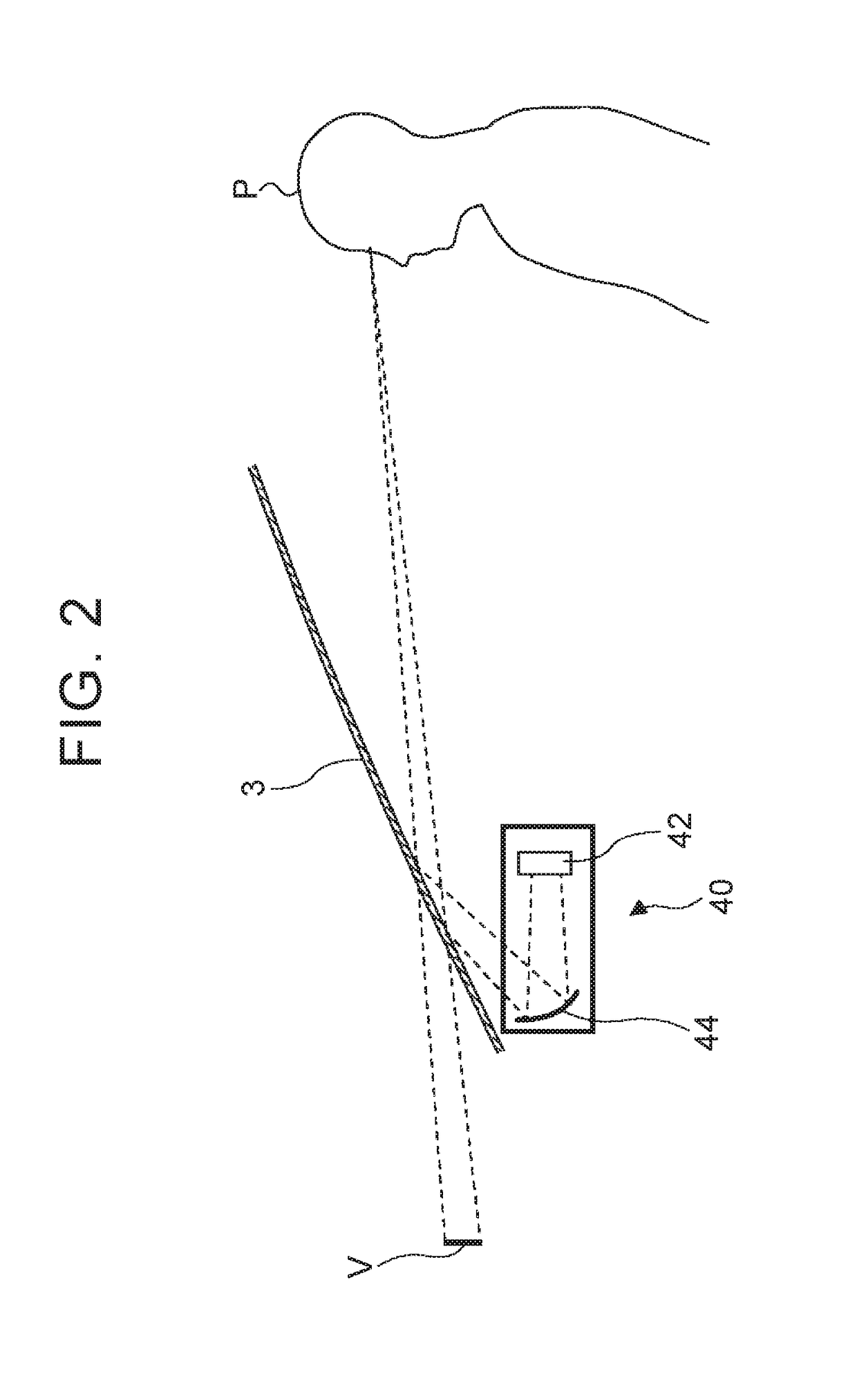
[0033]The display device 42 is incorporated in a head-up display (HUD) unit 40. An example of the HUD unit 40 will be described with reference to FIG. 2.

[0034]The vehicle sp...


PUM


Abstract

A vehicular information display apparatus includes: a head-up display unit and a controller configured to change an arrangement of information in the vehicle information image that includes vehicle information image that includes a first region, and a second region. The first region includes a first image portion representing current vehicle speed information. The first image portion includes a vehicle speed value display representing a vehicle speed value, and a unit display representing a unit of the vehicle speed value. The controller is configured to set a position of the vehicle speed value display such that the position of the vehicle speed value is left-aligned in the first region, and configured to change a position of the unit display to a position directly below a rightmost numeral of the vehicle speed value display.

Description

INCORPORATION BY REFERENCE[0001]The disclosure of Japanese Patent Application No. 2015-238889 filed on Dec. 7, 2015 including the specification, drawings and abstract is incorporated herein by reference in its entirety.BACKGROUND[0002]1. Technical Field[0003]The disclosure relates to a vehicular information display apparatus.[0004]2. Description of Related Art[0005]A head-up display unit that displays a vehicle information image in the driver's forward field of view is known (see, for example, Japanese Patent Application Publication No. 2015-141161 (JP 2015-141161 A)). The vehicle information image includes a plurality of image portions respectively representing different kinds of vehicle information, such as a vehicle speed and route guidance information.[0006]The size of the vehicle information image displayed, by the head-up display unit, in the driver's forward field of view is restricted due to, for example, the restriction on the size of the head-up display unit itself.[0007]F...

Claims


Application Information

Patent Timeline
IPC IPC(8): G02B27/01B60K35/00G06F3/01
CPCG02B27/0179G06F3/011G02B27/0101B60K35/00B60K2350/1076G02B2027/0183B60K2350/2052B60K2350/352B60K2350/92G02B2027/014G01C21/3635G01C21/365G02B27/01G02B2027/0141B60K2370/186B60K2370/119B60K2370/1529B60K2370/191B60K2370/172B60K2370/166B60K2370/70B60K2370/334B60K2370/52
Inventor MURAMATSU, SHIGETOKUMON, HITOSHI
Owner TOYOTA JIDOSHA KK
Why Eureka
Try Eureka