System for holding a forward pressure bulkhead via non-parallel rods attached to the floor

a technology of forward pressure and pressure bulkhead, which is applied in the direction of fuselage bulkheads, aircraft accessories, fuselages, etc., can solve the problems of inability to work in the work area in standing position, the volume of the compartment is encumbered, and the forward pressure bulkhead providing the separation between the spaces with different pressures is exposed to considerable loads

Active Publication Date: 2017-06-15
AIRBUS OPERATIONS (SAS)
View PDF8 Cites 0 Cited by
  • Summary
  • Abstract
  • Description
  • Claims
  • Application Information

AI Technical Summary

Benefits of technology

[0009]To do this, this invention proposes a nose section of an aircraft in which there is a flat surface forward pressure bulkhead, characterized in that the bulkhead includes at least one transverse frame and in that the nose section includes at least two rods, of which one of the front ends is attached to the bulkhead and / or to the frame and the other rear end is attached to a structural element, the two rods getting further apart from each other when moving from one end to the other end, thus providing a work space.
[0010]Therefore, the rods provide a comfortable work area allowing access to a large majority of the equipment units, while picking up part of the loads from the pressure bulkhead to the structural element.

Problems solved by technology

The forward pressure bulkhead providing the separation between the spaces with different pressures is exposed to considerable loads.
When assembling an aircraft, operatives have to accommodate a large number of equipment units (fittings, cables and pipes) in the volume of the technical compartment: however, the volume of the compartment is encumbered, exiguous and difficult to reach.
Furthermore, on account of the size of the majority of aircraft, operatives cannot work in these work areas in a standing position.
It is therefore difficult to operate in the space of the front technical compartment, and this obliges the operatives to install the different equipment units progressively, unit after unit.
This results in a long and fastidious assembly process.

Method used


Image

  • System for holding a forward pressure bulkhead via non-parallel rods attached to the floor
  • System for holding a forward pressure bulkhead via non-parallel rods attached to the floor
  • System for holding a forward pressure bulkhead via non-parallel rods attached to the floor

Examples


Embodiment Construction

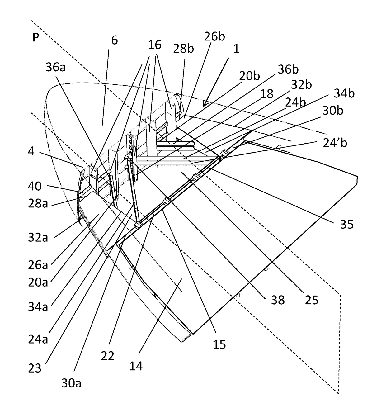
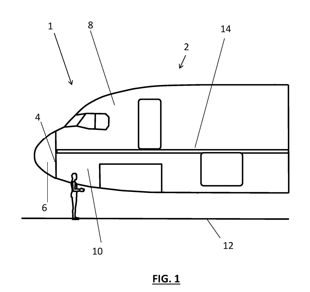
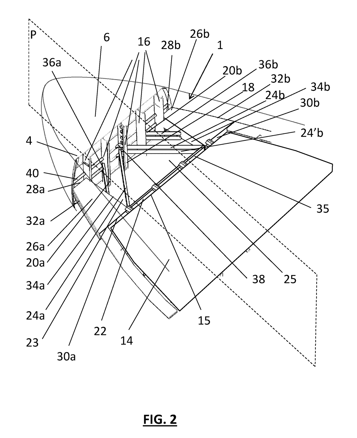
[0025]FIG. 1 shows a front part 1 of a nose section of an aircraft 2. The part 1 comprises a forward pressure bulkhead 4. The bulkhead 4 separates a radome 6, which is a non-pressurized space on one hand, from a cockpit 8 and a working technical compartment 10, which are pressurized spaces on the other.

[0026]In the embodiment of FIG. 1, the aircraft 2 is assumed to be placed on a ground 12 defining a horizontal plane. The aircraft comprises a floor 14 placed so as to be parallel to the ground 12, namely on a horizontal plane. The floor 14 is a walking floor for the members of the crew (pilot, hostesses etc.) and / or for the passengers. It can be limited to the cockpit floor or be further extended from the cockpit floor at least in part to the cabin floor or any other walking floor. A vertical direction is a direction perpendicular to the horizontal planes of the ground 12 and the floor 14.

[0027]The cockpit 8 and the technical compartment 10 are vertically separated by the floor 14. T...


PUM


Abstract

A zone provided between the forward pressure bulkhead in an aircraft and the floor. The nose section of the aircraft in which the flat surface pressure bulkhead including at least one transverse frame comprises at least two rods, of which one of the front ends is attached to the bulkhead and / or the frame and the other rear end is attached to a structural element, the two rods further apart from the front to the rear, thus providing a work space. Therefore, the rods provide a more comfortable work area while picking up part of the loads from the bulkhead to the floor.

Description

CROSS-REFERENCES TO RELATED APPLICATIONS[0001]This application claims the benefit of the French patent application No. 1562240 filed on Dec. 11, 2015, the entire disclosures of which are incorporated herein by way of reference.BACKGROUND OF THE INVENTION[0002]This invention relates to a system for holding a pressure bulkhead and the aircraft provided with such a system.[0003]The nose section of an aircraft fuselage comprises on one hand, a separation bulkhead between a radome which is a non-pressurized space, and on the other, a cockpit and a front technical compartment adjacent to the cockpit and below the latter, which are pressurized spaces. This separation bulkhead is more commonly called the forward pressure bulkhead.[0004]The forward pressure bulkhead providing the separation between the spaces with different pressures is exposed to considerable loads. It is therefore attached directly to the floor in such a way that the floor picks up part of the loads exerted by the pressure...

Claims


Application Information

Patent Timeline
Patent Type & Authority Applications(United States)
IPC IPC(8): B64C1/10B64C1/36B64C1/18
CPCB64C1/10B64C1/36B64C1/18B64C1/061B64C1/064
Inventor GUERING, BERNARD
Owner AIRBUS OPERATIONS (SAS)
Why Eureka
Try Eureka