Drywall corner bead cutting device

a cutting device and corner bead technology, which is applied in the field of drywall corner bead cutting devices, can solve the problems of difficult cutting of drywall corner bead to correctly produce these corner joints, time-consuming process, and cutters without much experience, so as to reduce the possibility of an incorrect cut, accurately determine, and reduce the effect of the skill level of drywallers

Inactive Publication Date: 2006-05-11
WINKLER BARBARA
View PDF7 Cites 1 Cited by
  • Summary
  • Abstract
  • Description
  • Claims
  • Application Information

AI Technical Summary

Benefits of technology

[0016] The present invention as thus described provides many improvements to the drywall corner bead cutting methods which were previously used. For example, the cutting skill level of the drywaller becomes less important as the present invention is designed to make accurate, repeatable cuts each and every time the invention is used. Also, because the drywall corner bead is slid into the invention, the correct positioning of the drywall corner bead within the invention for the cut can be accurately determined after the initial measurement is made, thus greatly reducing the possibility of an incorrect cut at an incorrect location being made. Furthermore, because the cutting blade of the present invention is movably mounted to the retaining body, it is not used in a “freehand” manner, thus greatly reducing the possibility for injury which often occurs when using a sharp cutting blade to cut a piece of plastic such as the drywall corner bead. Finally, because the present invention includes relatively few moving parts, the expected useable life span for the invention is quite long and it should be relatively inexpensive to manufacture, thus making it available for a vast majority of drywall erectors in the industry. It is thus seen that the present invention provides a substantial improvement over those devices and methods found in the prior art.

Problems solved by technology

Once of the problems encountered in the use of drywall, however, is that the drywall must be fitted around windows which are built into the sides of the building, thus requiring sections of the drywall to be cut out to permit the window to be seen therethrough.
One of the disadvantages of the use of drywall corner bead, however, is that the corner angles of the window frame must be accommodated by the drywall corner bead to permit the adjacent sections of the drywall corner bead to butt against one another to provide a seamless and generally continuous wall surface adjacent the window.
The cutting of the drywall corner bead to correctly produce these corner joints can be quite difficult, however, and cutters without much experience often make mistakes in making the corner cuts.
Of course, this process is very time consuming and the final product is only as good as the person following the pencil line with the snips.
There is enormous variation in the skill level of persons practicing drywalling, and it is clear that the above-described process provides many opportunities for mistakes to be made which would result in the need for the cutter to begin again, thus increasing the length of time needed to complete the process and resulting in far more waste due to production of unuseable sections.

Method used


Image

  • Drywall corner bead cutting device
  • Drywall corner bead cutting device
  • Drywall corner bead cutting device

Examples


Embodiment Construction

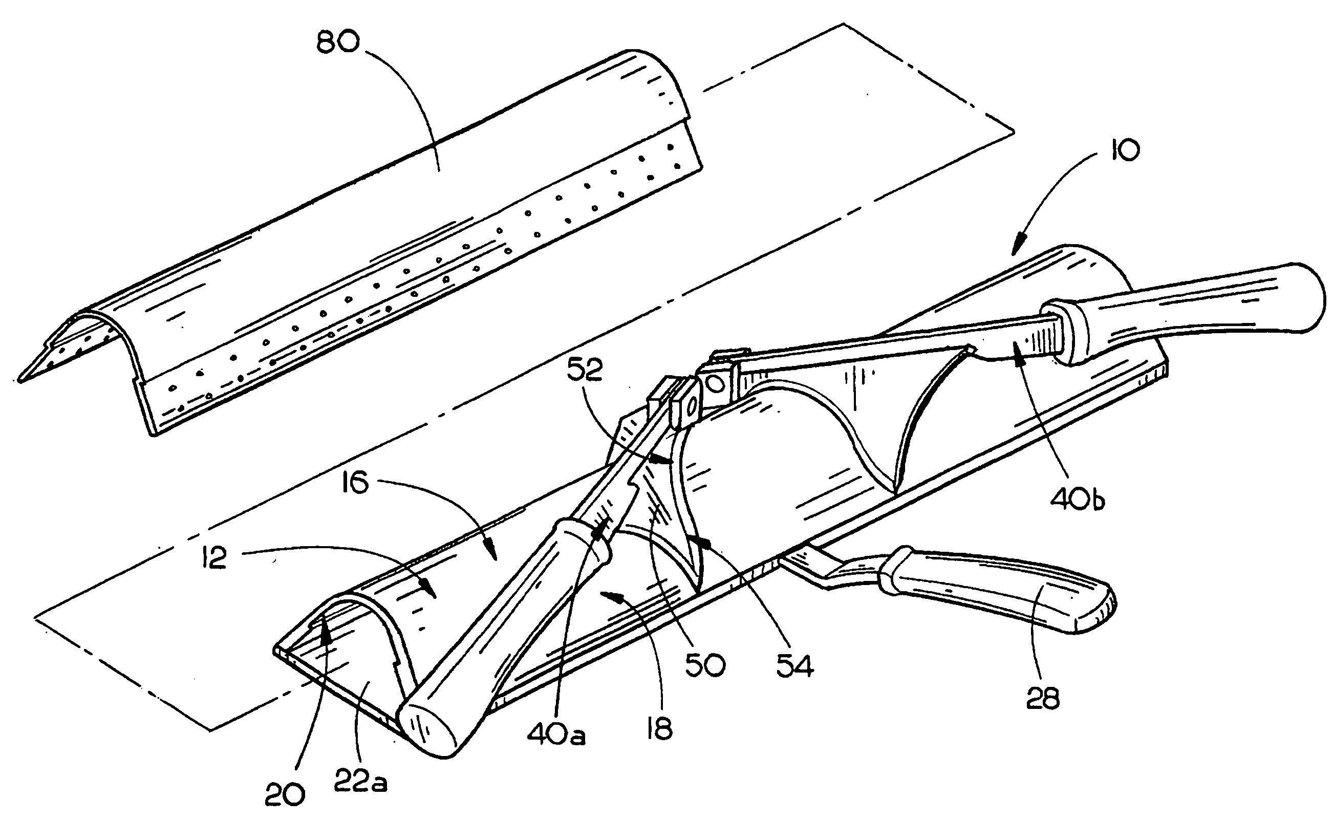
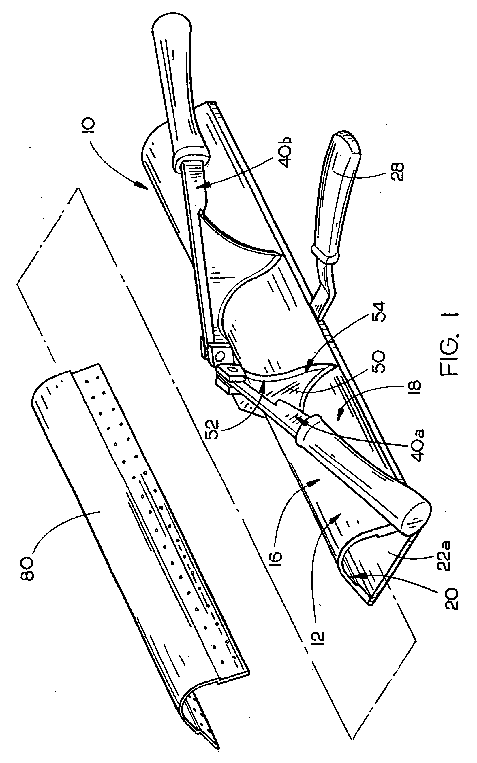
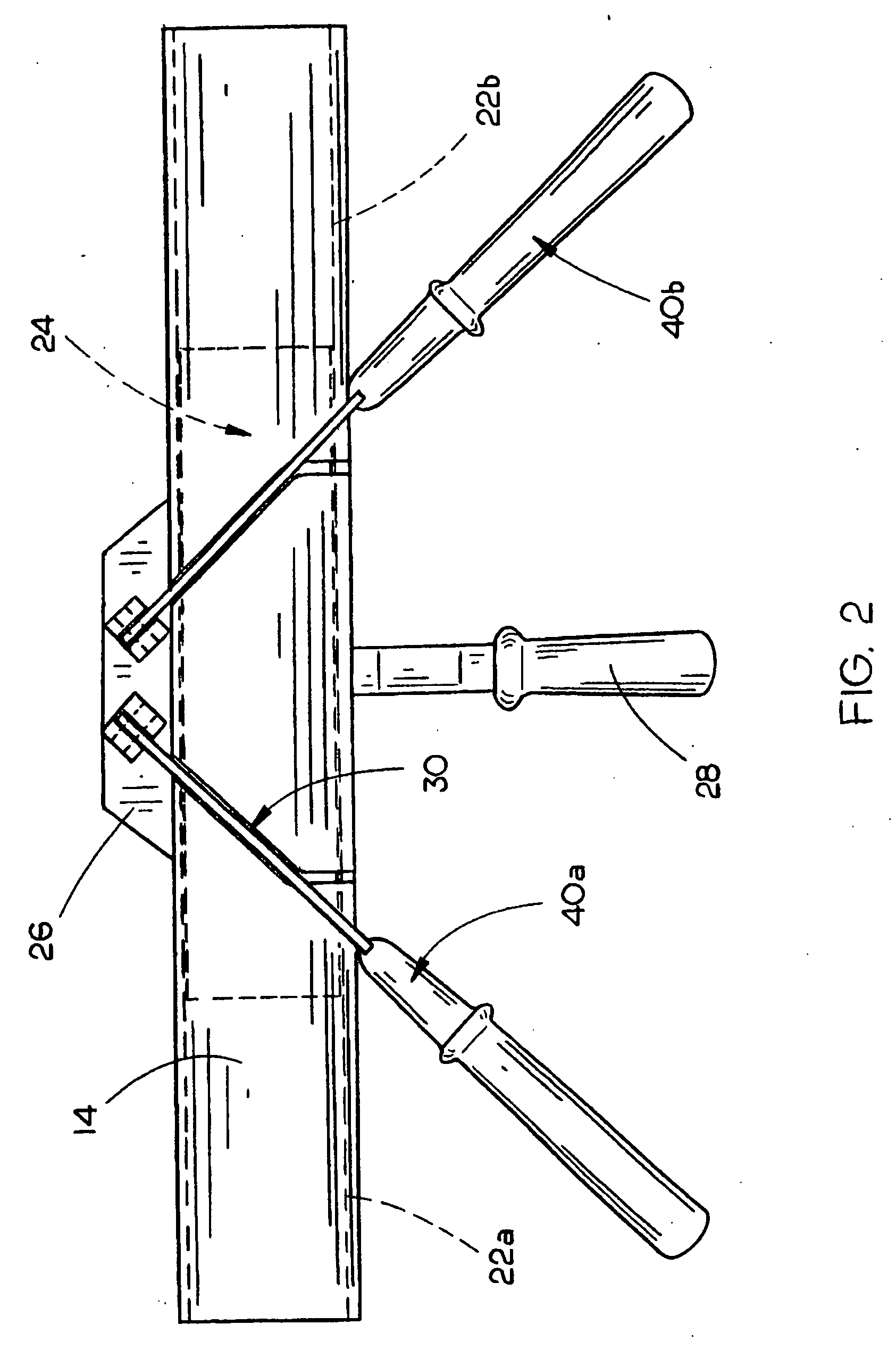
[0023] The drywall corner bead cutting device 10 of the present invention is shown best in FIGS. 1-3 as including a drywall corner bead retaining body 12 and two cutting blade assemblies 40a and 40b which are pivotably mounted on the retaining body 12 as will be described later in this disclosure. In the preferred embodiment, the retaining body 12 would include a longitudinally extended top wall plate 14 having a length of approximately 6 to 12 inches and a width of approximately 1 to 4 inches, and the top wall plate 14 would preferably be constructed of a sturdy sheet metal or the like. Top wall plate 14 preferably includes three integrally connected sections, a top section 16 having a generally arcuate cross-sectional shape, a lower inner wall plate section 18 extending downwards and inwards from the top section 16 and a lower outer wall plate section 20 which extends downwards and outwards from the top section 16 as shown best in FIGS. 1 and 3. In the preferred embodiment, lower ...


PUM


Abstract

A drywall corner bead cutting device includes a drywall corner bead retaining body having a cross-sectional shape approximately similar to the cross-sectional shape of the drywall corner bead to be cut, the retaining body including a longitudinally extended top wall plate and inner and outer base wall retaining elements for releasably retaining the drywall corner bead within the retaining body and at least one cutting blade assembly movably mounted on the retaining body which includes a handle and a cutting blade which extends through the retaining body to cut the drywall corner bead on a diagonal to permit the cut sections of drywall corner bead to be butted against one another to form a generally seamless joint.

Description

BACKGROUND OF THE INVENTION [0001] 1. Technical Field [0002] The present invention is directed to drywalling tools and, more particularly, to a drywall corner bead cutting device which includes a drywall corner bead retaining body having a cross-sectional shape approximately similar to the cross-sectional shape of the drywall corner bead to be cut, the retaining body including a longitudinally extended top wall plate and inner and outer base wall retainers for releasably retaining the drywall corner bead within the retaining body and at least one cutting blade assembly movably mounted on the retaining body which includes a handle and a cutting blade which extends through the retaining body to cut the drywall corner bead on a diagonal to permit the cut sections of drywall corner bead to be butted against one another at a joint. [0003] 2. Description of the Prior Art [0004] A vast majority of buildings which are constructed in the United States use drywall to form the interior walls o...

Claims


Application Information

Patent Timeline
Patent Type & Authority Applications(United States)
IPC IPC(8): B26B3/08B26B1/00
CPCB26D1/30B26D3/162
Inventor WINKLER, BARBARA
Owner WINKLER BARBARA
Why Eureka
Try Eureka