Multi-sided heat exchangers with compliant heat transfer surfaces

Active Publication Date: 2017-06-22
DANA CANADA CORP
View PDF3 Cites 62 Cited by
  • Summary
  • Abstract
  • Description
  • Claims
  • Application Information

AI Technical Summary

Benefits of technology

[0034]In an embodiment, the heat exchanger includes a plurality of support elements in the fluid flow passageway, and wherein each of said support elements comprises a rib or a dimple having a base which is joined to one of the first and second plates and a free end which is proximate to and/or in contact with the other of the first and second plates; wherein a proportion of a total surface area of the first flow channel occupied by the support elements is less than a proportion of a total surface area of the second flow channel occupied

Problems solved by technology

Such batteries can generate large amounts of heat that needs to be dissipated.
Providing a single plate cooler in contact with the through-plane faces of the battery cells along one side of the battery pack does not, however, provide uniform cooling, and can result in significant temperature non-uniformity within the cell.
While temperature uniformity can be improved by providing plate coolers along more than one face of the battery pack, the provision of multiple plate coolers requires a large number of coolant connections, which increases complexity, manufacturing cost, and the chance of leakage at a failed joint.
However, achieving adequate

Method used


Image

  • Multi-sided heat exchangers with compliant heat transfer surfaces
  • Multi-sided heat exchangers with compliant heat transfer surfaces
  • Multi-sided heat exchangers with compliant heat transfer surfaces

Examples


first embodiment

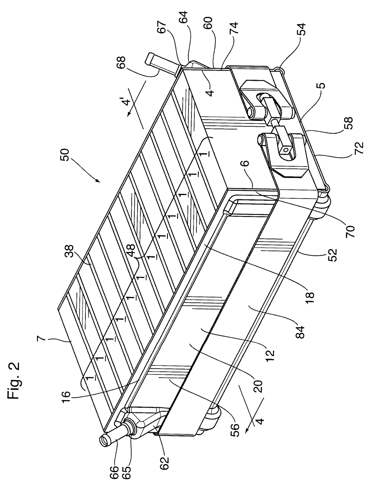
[0056]A heat exchanger 50 is now described below with reference to FIGS. 2 to 9.

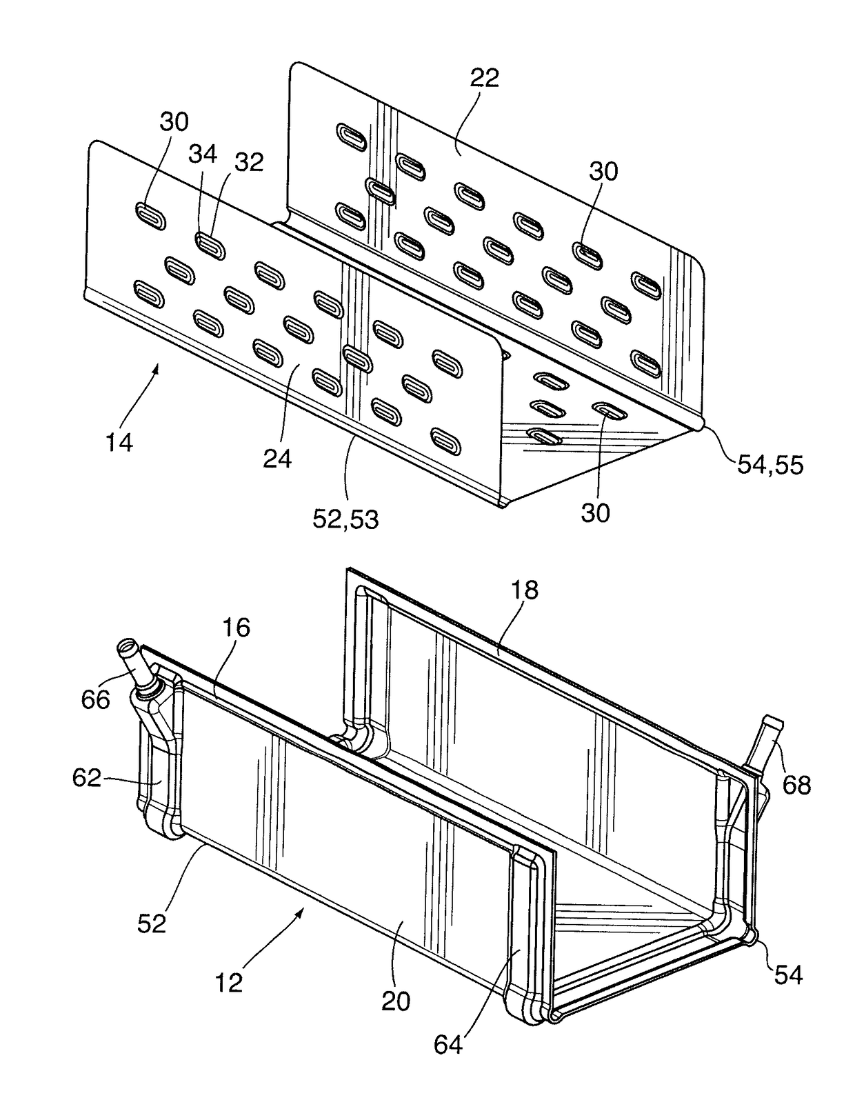
[0057]Heat exchanger 50 is an example of a panel-type heat exchanger having one or more linear bends so as to define a multi-faceted heat exchanger structure comprising a plurality of fluid-carrying panels, wherein each of the panels comprises one facet of the overall structure. In this embodiment, there are two linear bends 52, 54 which are parallel to one another and spaced apart from one another. The bends 52, 54 each form an angle of about 90°, and together define an open-ended, three-sided enclosure comprising first, second and third fluid-carrying panels 56, 58, 60. The first and third fluid-carrying panels 56, 60 comprise opposed sides of the three-sided enclosure and the second fluid-carrying panel 58 comprises the base of the enclosure.

[0058]In heat exchanger 50, each of the fluid-carrying panels 56, 58, 60 has an inwardly facing side and an outwardly facing side. The inwardly facing sides of f...

second embodiment

[0087]A heat exchanger 100 is now described with reference to FIGS. 10 to 12. Heat exchanger 100 shares a number of elements in common with heat exchanger 50. Like reference numerals are used to refer to like elements in the following description and in the drawings, and the above description of these elements in connection with heat exchanger 50 also applies to heat exchanger 100.

[0088]Heat exchanger 100 includes two linear bends 52, 54 so as to define an open-ended three sided enclosure comprising three fluid-carrying panels 56, 58, 60. As in heat exchanger 50, the inwardly facing sides of the fluid-carrying panels are defined by the second plate 14 and the outwardly facing sides are defined by the first plate 12.

[0089]The main difference between the heat exchangers 50 and 100 is that heat exchanger 100 has its first and second manifolds 62, 64 defined on the inside of the three-sided enclosure, such that the first and second manifolds 62, 64 are formed on the second plate 14 rat...


PUM


Abstract

A heat exchanger for a battery has fluid-carrying panels and defines a multi-sided enclosure for enclosing at least two sides of the battery. The heat exchanger has first and second fluid-carrying panels defining first and second flow channels, where the first and second fluid-carrying panels are arranged at an angle to another. The heat exchanger may also include a third fluid-carrying panel defining a third flow channel, and being arranged at an angle to the second fluid-carrying panel. The heat exchanger has first and second plates sealingly joined together along their peripheries and defining a fluid flow passageway between their central fluid flow areas. The second plate may be compliant, its central fluid flow area being deformable away from the central fluid flow area of the first plate in response to a pressure of a fluid inside the fluid flow passageway.

Description

CROSS-REFERENCE TO RELATED APPLICATION[0001]This application claims priority to and the benefit of U.S. Provisional Patent Application No. 62 / 017,871 filed Jun. 27, 2014, the contents of which are incorporated herein by reference.FIELD OF THE INVENTION[0002]The invention generally relates to heat exchangers, and particularly to heat exchangers comprising two or more fluid-carrying panels for cooling heat-generating elements such as prismatic lithium-ion battery cells.BACKGROUND OF THE INVENTION[0003]Rechargeable batteries such as batteries made up of many lithium-ion cells can be used in many applications, including for example in electric vehicle (“EV”) and hybrid electric vehicle (“HEV”) applications. Such batteries can generate large amounts of heat that needs to be dissipated.[0004]A common type of lithium-ion battery cell is a hard shelled, prismatic cell having a generally rectangular prismatic shape, with six square or rectangular faces which meet at angular or rounded corner...

Claims


Application Information

Patent Timeline
IPC IPC(8): F28D1/06F28F3/12F28F9/00H01M2/10H01M10/647H01M10/625H01M10/6556F28F3/04H01M10/0525H01M50/209
CPCF28D1/06F28F3/044F28F3/12F28F9/00H01M10/0525H01M2220/20H01M10/625H01M10/6556H01M2/1077F28D2021/0028F28F2240/00H01M10/647H01M10/6567H01M10/613F28F2275/08F28F3/042F28F9/0248F28D2021/0029Y02E60/10H01M50/209Y02P70/50Y02T10/70
Inventor PALANCHON, HERVEKENNEY, BENJAMIN A.SO, ALLAN K.
Owner DANA CANADA CORP
Why Eureka
Try Eureka