
Sonde having orientation compensation for improved depth determination

a technology of orientation compensation and depth measurement, which is applied in the direction of measurement devices, instruments, scientific instruments, etc., can solve the problems of small percentage error in depth measurement, small error at smaller depths, and limited application, so as to facilitate the removal of pressure sensors and free up space for other sensors. , the effect of long deployment times

Active Publication Date: 2017-06-22
INSITU INC
View PDF3 Cites 14 Cited by
  • Summary
  • Abstract
  • Description
  • Claims
  • Application Information

AI Technical Summary

Benefits of technology

The patent text describes a system and method for accurately determining the depth of a sonde device, even when the sonde is not vertically aligned. This is achieved by positioning a pressure sensor in the sonde body and using an orientation sensor to accurately calculate depth. The sensors are designed with notches that allow for automated cleaning and anti-fouling, and a double-sided wiper keeps the sensor plane obstruction-free. The technical effects of this system and method include improved accuracy and reliability of sonde depth measurements, as well as improved cleaning and anti-fouling capabilities.

Problems solved by technology

While such small-diameter and compact sondes provide a number of benefits, they are accordingly limited in the number of sensors that may be arranged at a common sensor surface and corresponding sensor plane.
Although at very large depths the percentage error in depth measurement may be small, the error becomes significant and substantial at smaller depths associated with shallower fluid applications, including groundwater applications.
While there is no orientation-associated depth error for a sonde remaining in true correct vertical alignment, such an orientation is not realistic during actual use where there may be fluid motion disturbing the sonde and affecting orientation change during use.
Accordingly, accurate depth measurement is challenging as the sonde tends to not remain consistently in a straight up and down configuration due to current in the water, movement at the surface such as being attached to a boat, ship or a person, touching debris or the bottom surface over which the fluid is located, or other interaction that perturbs sonde orientation.

Method used


Image

  • Sonde having orientation compensation for improved depth determination
  • Sonde having orientation compensation for improved depth determination
  • Sonde having orientation compensation for improved depth determination

Examples


example 1

h Pressure Sensor in the Body Separated from a Sensor Plane

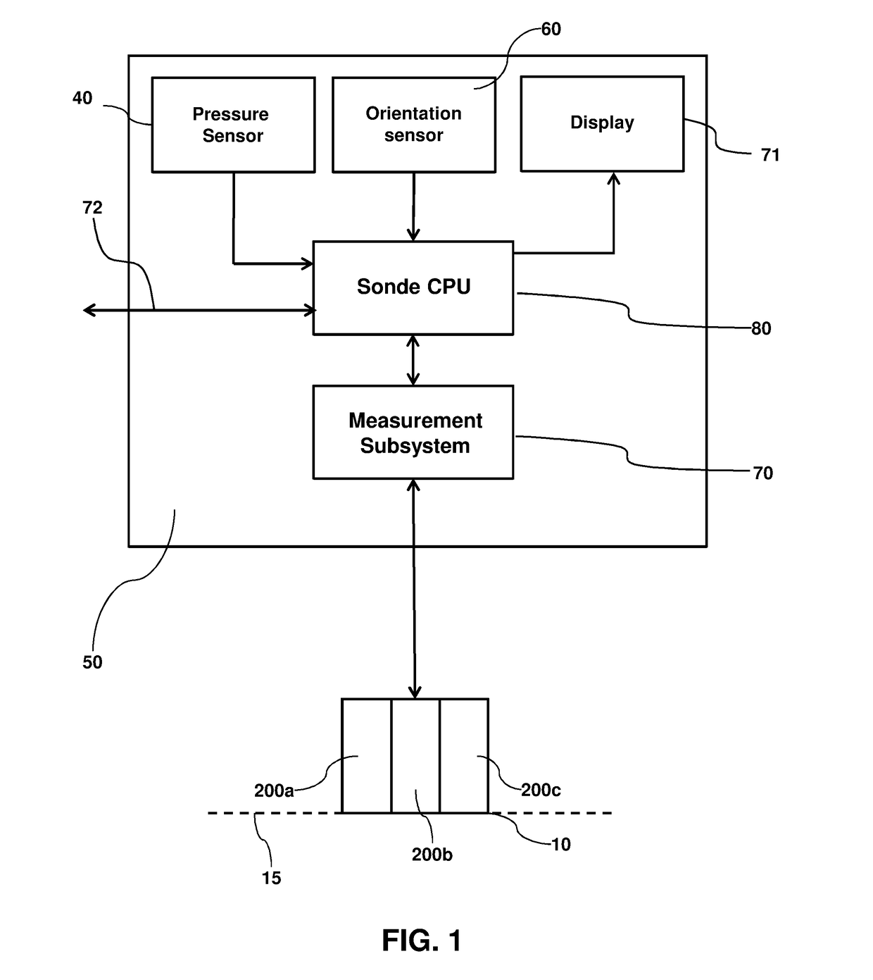
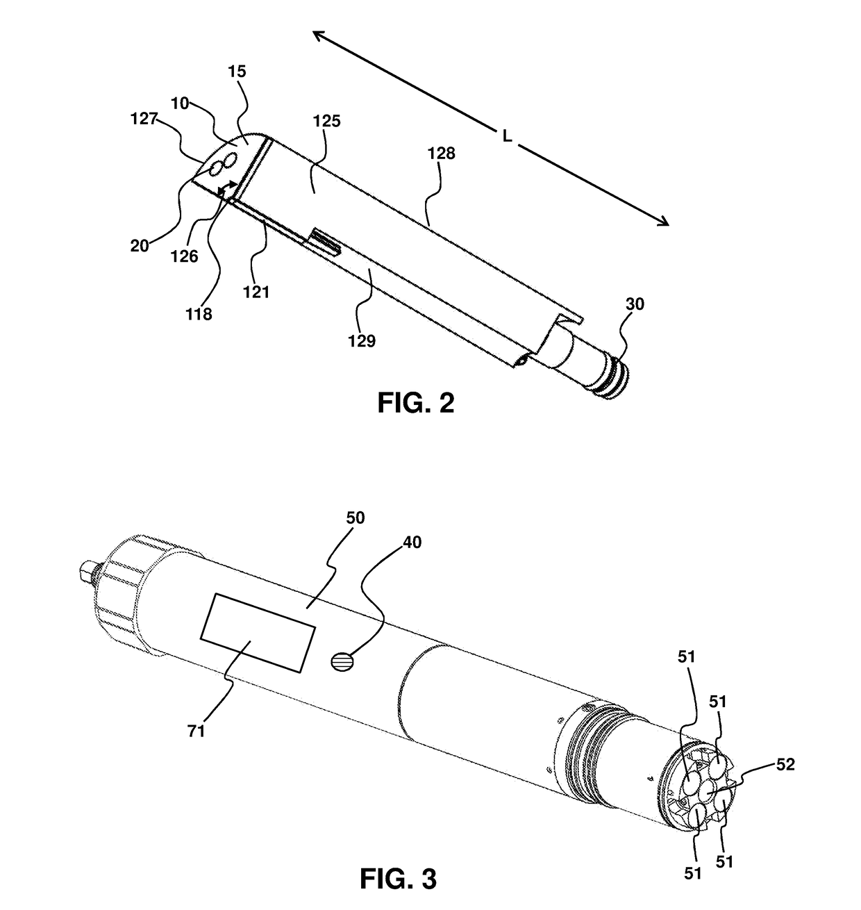
[0044]FIG. 1 provides a block diagram of a sonde with the pressure sensor 40 in the base 50 of the sonde to allow for additional sensors 200abc, with each distal end 10 of the sensor together forming the sensor plane 15 along the distal sensing surface. To distinguish from sensors 4060 in the sonde base 50, sensors 200a 200b 200c are also referred herein as longitudinally-extending or longitudinal sensor to emphasize the sensor plane 15 separated relative to the base. The sonde base 50 may contain a pressure sensor 40 and an orientation sensor 60. The base 50 is operably connected to at least one sensor, here represented by three sensors as 200a, 200b, and 200c. The three sensors form a sensor plane 15 as indicated by the dashed line along the distal sensing end 10 of the sensors. The sensors 200abc, the pressure sensor 40, and the orientation sensor 60 all provide data to a central processing unit (CPU) 80, optionally this ...

example 2

a Vertical Orientation

[0048]In ideal conditions, the sonde may be deployed such that it is perpendicular to the surface of the water and the base and sensor units are vertically aligned as illustrated in FIG. 5. In these conditions, determining the actual depth, D, of the sensor plane is straightforward. The pressure sensor 40 uses hydrostatic pressure to determine its depth relative to the water surface, Dp. Because the base and sensors are vertically aligned, the depth of the sensor plane with respect to the depth of the pressure sensor, Ds, is merely the length of the sensors 200 plus the length of the base between the pressure sensor 40 and the connection point between the sensor and the base. Thus, the depth of the sensor plane D is merely the sum of Dp and Ds. As desired, pressure and depth may be determined from each other, such as by the hydrostatic equation for pressure, P=ρgh, where ρ is fluid density, g is the acceleration due to gravity, and h is the fluid depth.

example 3

an Offset-Orientation During Use

[0049]In practical deployment, the sonde is often not in perfect vertical alignment due to external factors such as water current, trolling along the water surface, such as by a moving boat, touching the bottom surface, or protrusions from the bottom surface. FIG. 6 illustrates a sonde that is deployed at an angle 8 #90°, whereas in FIG. 5θ=90°. In this situation, adding Dp and Ds no longer accurately provides the depth of the sensor plane. Instead, the orientation angle, θ, is necessary to calculate the actual depth which may be determined using an orientation sensor 60, for example, a digital three-axis accelerometer.

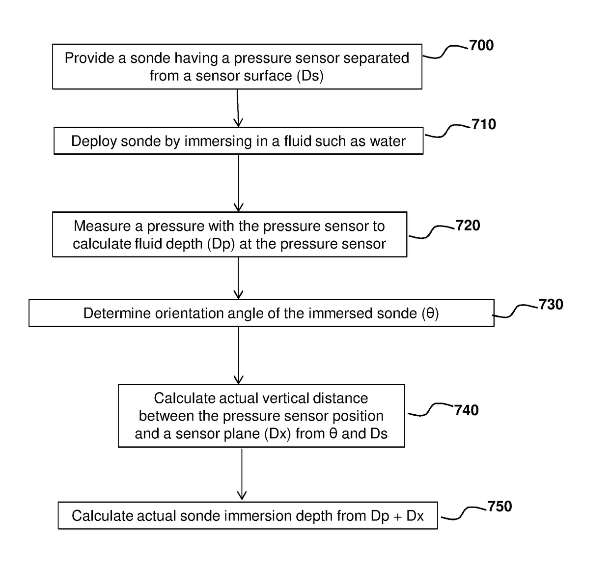
[0050]In this situation, the actual depth of the sensor plane, D, is defined by the relationship Dp+Dx where Dx=Ds sin θ, so that in FIG. 5, for θ=90° Dx=Ds, whereas in FIG. 6, Dx≠Ds. The orientation angle, θ, can be measured with an orientation sensor (60), such as a three-axis accelerometer, so that the actual depth of the sonde senso...


PUM


Abstract

Provided herein are sondes having a pressure sensor that is separated from active sensing portions of the other sonde sensor or sensors by a longitudinal distance along the sonde. The pressure sensor may be positioned in the base portion of the sonde, with removable sensors connected thereto with a sensor plane at a distal end of the sensors that measures any number of parameters associated with the liquid in which the sonde is immersed. An orientation sensor positioned in the base portion determines an orientation angle of the sonde that, in combination with the depth determined at the pressure sensor location by the pressure sensor, provides the ability to determine the actual depth of the sensor plane, irrespective of orientation angle. Accordingly, improved depth measurement is achieved, without having to confine placement of the pressure sensor at the sensor plane.

Description

CROSS-REFERENCE TO RELATED APPLICATIONS[0001]This application claims the benefit of U.S. Provisional Patent Application No. 62 / 271,198 filed Dec. 22, 2015, which is specifically incorporated by reference to the extent not inconsistent herewith.BACKGROUND OF INVENTION[0002]Provided herein are compact sondes having a small diameter form factor and accurate depth measurement without sacrificing the number of water parameters capable of being measured by sensors arranged along a sensor plane.[0003]In a small diameter submersible multiparameter sonde, space constraints and limitations can make it challenging to align all sensors to a common sensor plane. Although a pressure sensor used to measure depth is a good candidate to locate elsewhere on the sonde, challenges arise with such a configuration. For example, positioning a pressure sensor away from the common sensor plane can result in significant errors in determining the actual depth of the sensor plane as the sonde moves and orients...

Claims


Application Information

Patent Timeline
Patent Type & Authority Applications(United States)
IPC IPC(8): G01B21/18
CPCG01N33/1886G01B21/18
Inventor STEINBACH, ASHLEYMCKEE, DUANE B.
Owner INSITU INC
Learn More