Autonomous device with biofouling control and method for monitoring aquatic environment

a technology of autonomous devices and biofouling, which is applied in the direction of valve operating means/releasing devices, process and machine control, instruments, etc., can solve the problems of insufficient soluble anti-biofouling paints, inability to directly apply anti-biofouling paints to sensors, and insufficient biofouling prevention. , to achieve the effect of increasing the efficiency of stirring propeller, rapid and even dispersal of biocide matter, and long deployment times

Inactive Publication Date: 2013-01-17
KELLY VINCENT M +2
View PDF1 Cites 13 Cited by
  • Summary
  • Abstract
  • Description
  • Claims
  • Application Information

AI Technical Summary

Benefits of technology

[0027]Preferably, the source of biocide or anti-fouling matter is a biocide reservoir surrounding a stirring propeller for even dispersal of a dense biocide solution or slurry throughout the closed sampling chamber. In a preferred embodiment, the biocide reservoir comprises an outer sleeve and an inner sleeve arranged substantially concentric with respect to the outer sleeve and having a closable upper end and a closed lower end which establish an annular reservoir space filled with biocide matter, the reservoir further comprising a biocide outlet means and vent in fluid communication with the chamber. The inner sleeve defines a central opening in the reservoir which is configured and adapted to extend radially around the stirrer blades of the propeller for rapid and even dispersal of the biocide matter.
[0028]The toroid shape of this reservoir increases the efficiency of the stirring propeller because it surrounds the propeller as a ducted fan or kort nozzle, and because it incorporates valves that permit ambient water to enter and leave the reservoir, the reservoir can contain a large charge of biocide that is gradually dissolved by ambient water, thus allowing long deployment times. The provision of upper and lower valves to this reservoir permits bubbles that may be formed in the reservoir to be released upwards and a dense charge of biocide infused water to be released downwards. Ambient water enters the reservoir in small amounts during both of these processes and dissolves more biocide that can be released during the next cycle.
[0029]The sensor envelope is preferably formed as a housing with one or several windows which are controllably opened / closed in accordance with the sampling cycle of the sensors. The housing may be implemented as a double-wall structure having an outer cup and an inner cup positioned in concentric relationship with each other and each having a plurality of openings of predetermined dimensions, and positioned at predetermined positions on the walls of the inner and outer cups. The controller changes a relative disposition between the inner and outer cups in synchrony with the sampling cycle of the sensors in order to control the relative disposition between the openings on the walls of the inner and outer cups, thereby controlling the extent of “openness / closeness” of the chamber to the aquatic environment.

Problems solved by technology

However, biofouling remains a major problem that to date has not been adequately addressed.
Biofouling is, for a large percentage of instrumentation deployments, the single biggest factor affecting the operation, maintenance, and data quality of in-water monitoring sensors, and therefore biofouling prevention for sensor systems is considered a major issue in aquatic environment monitoring.
Anti biofouling paints cannot be put directly on the sensors and may not be sufficiently soluble to provide a “halo” effect that will protect the sensors.
In addition, anti-biofouling paints can sometimes accumulate films that could inhibit sensor performance, after short periods of immersion.
However, the anti-fouling paints are extremely toxic and thus are harmful for living organisms, while wipers do not have the capability of complete prevention and removal of bio-fouling, thereby only partially addressing the bio-fouling problem.
These wipers can also become substrate for fouling organisms and thus scratch optically clear surfaces.
This is a time and cost consuming endeavor which makes aquatic environments monitoring extremely expensive and labor intensive.

Method used


Image

  • Autonomous device with biofouling control and method for monitoring aquatic environment
  • Autonomous device with biofouling control and method for monitoring aquatic environment
  • Autonomous device with biofouling control and method for monitoring aquatic environment

Examples


Embodiment Construction

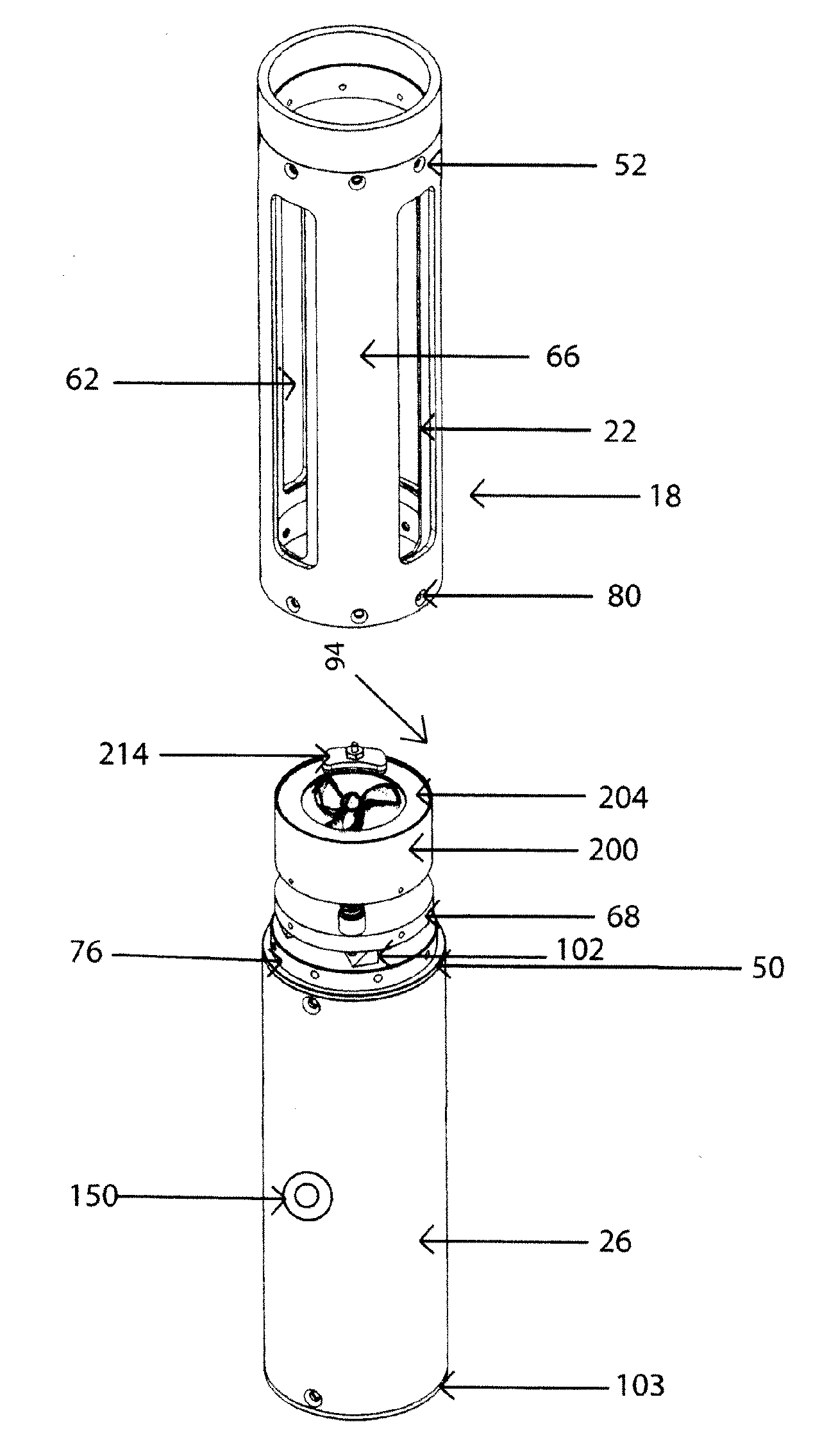
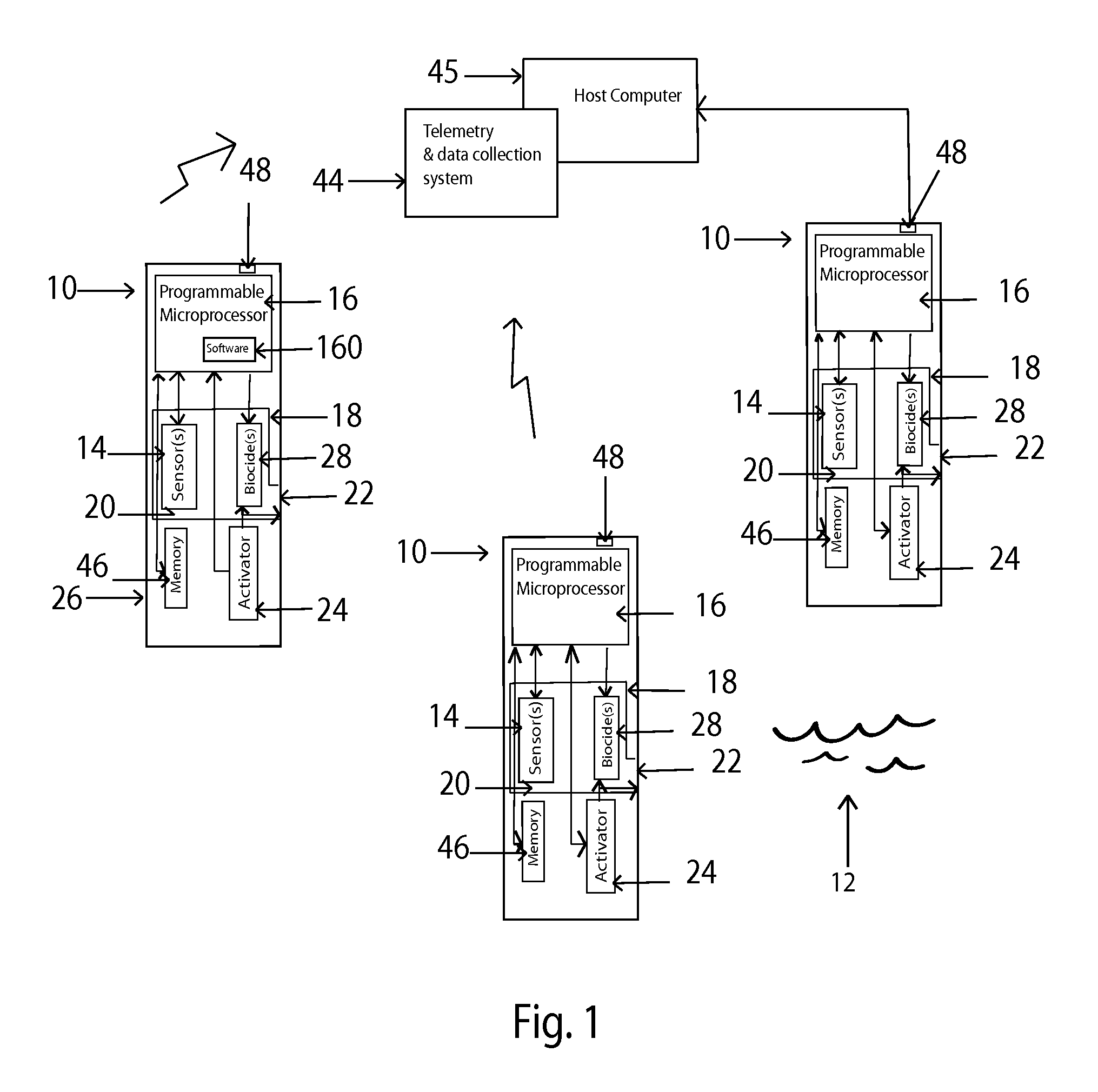
[0062]Referring to FIG. 1, a programmable autonomous device 10 is shown with biofouling control for monitoring fluid environment (for example aquatic environment or gaseous environment) 12 and is designed for deployment at a predetermined position in an aquatic environment for an extended period of time. Due to the anti-fouling control, the autonomous device 10 is capable of autonomous operation without the need for servicing for periods of one to several months.

[0063]The autonomous device 10 of the present invention may use any number of sensors 14 of a variety of types and is adapted to protect analog or serial sensors for measuring physical and chemical parameters of the water in the aquatic environment 12. As one of many possible examples, a multiprobe sensor instrument may be used with the autonomous device 10 of the present invention, such as multi-parameter Sondes YSI6600 for monitoring dissolved oxygen, chlorophyll, blue-green algae, turbidity, temperature, pH level, etc., a...


PUM


Abstract

A microprocessor preprogrammable autonomous device with biofouling control and method for monitoring aquatic environment by disposing environmental sensors in a sensor chamber which programmably opens for allowing direct communication between the sensors and the fluid of interest for sampling and which is closed after the sampling sequence is completed to create an anti-fouling environment in the sensor chamber by dissolving a biocide salt in the chamber and exposing the sensors to the anti-fouling environment for a predetermined period of time.

Description

REFERENCE TO RELATED APPLICATIONS[0001]This application is a Continuation-in-Part of U.S. patent application Ser. No. 12 / 187,787, filed Aug. 7, 2008, which claims priority to U.S. Provisional Patent Application 60 / 954,412 filed Aug. 7, 2007; the entire contents of which are incorporated herein by reference.FIELD OF THE INVENTION[0002]The present invention is directed to biofouling resistant apparatus and method for monitoring of fluid (aquatic and gaseous) environments, and particularly to pre-programmable autonomous devices with anti-biofouling capabilities deployed in aquatic environment for acquisition of data related to chemical, biological and physical conditions of the environment of interest.BACKGROUND OF THE INVENTION[0003]There is an ever increasing interest in the deployment of autonomous devices for monitoring biological, chemical and physical conditions in aquatic environments. This interest encompasses monitoring hydrographic conditions, fisheries, weather prediction, a...

Claims


Application Information

Patent Timeline
Patent Type & Authority Applications(United States)
IPC IPC(8): G05B17/00G06F17/00F16K31/00
CPCG01N1/18G01N1/2035G01N21/15G01N17/008G01N2001/021G01N2015/0088G01N2035/00881G01N33/18
Inventor KELLY, VINCENT M.CODISPOTI, LOUIS ANTHONYSUTTLES, STEVEN EDWARD
Owner KELLY VINCENT M
Why Eureka
Try Eureka