Motorcycle blind spot detection system and rear collision alert using mechanically aligned radar

a technology of blind spot detection and motorcycle, applied in the direction of scene recognition, pedestrian/occupant safety arrangement, instruments, etc., can solve the problems of not being able to use spot detection systems, and riding a motorcycle presenting an increased risk of collision with another vehicl

Active Publication Date: 2017-06-22
CONTINENTAL AUTONOMOUS MOBILITY US LLC
View PDF0 Cites 17 Cited by
  • Summary
  • Abstract
  • Description
  • Claims
  • Application Information

AI Technical Summary

Benefits of technology

[0012]In yet other embodiments, a camera may be mounted to the motorcycle, and is used in place of the accelerometer and gyroscope. The camera is operable for use with either the radar sensor, or the phased-array antenna assembly. The camera detects a change in position of the motorcycle relative to a road surface, such that the lean angle of the motorcycle is calculated, and t

Problems solved by technology

Because of the reduced ability to view surrounding vehicles when riding a motorcycle, the larger blind spot area, and the change in what is viewable in the side mirrors as the motorcycle is navigating a turn, riding a motorcycle therefore presents an

Method used


Image

  • Motorcycle blind spot detection system and rear collision alert using mechanically aligned radar
  • Motorcycle blind spot detection system and rear collision alert using mechanically aligned radar
  • Motorcycle blind spot detection system and rear collision alert using mechanically aligned radar

Examples


Embodiment Construction

[0026]The following description of the preferred embodiment(s) is merely exemplary in nature and is in no way intended to limit the invention, its application, or uses.

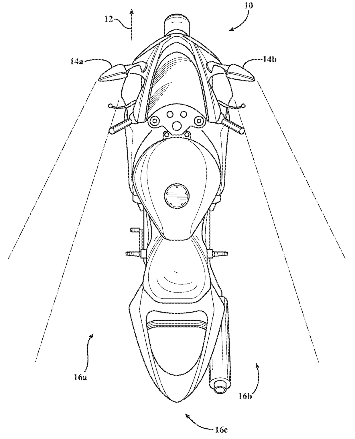
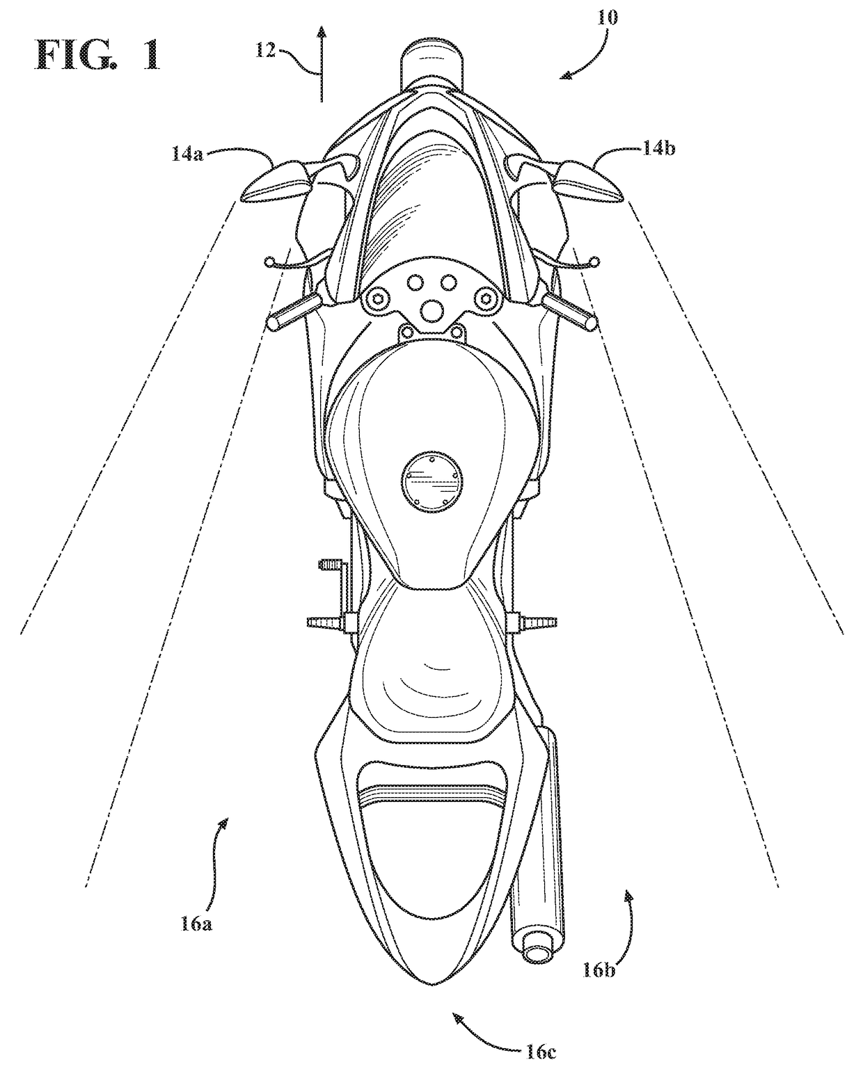
[0027]A diagram of a motorcycle having a blind spot detection system is shown in FIG. 1 generally at 10. When the rider of the motorcycle 10 is facing in a forward direction, as indicated by arrow 12, and uses either a first side mirror 14a or a second side mirror 14b, there several areas around the motorcycle 10 which are not visible to the rider. More specifically, there is a first blind spot area, shown generally at 16a, and a second blind spot area, shown generally at 16b, on each side of the motorcycle 10. There is also a rear area, shown generally at 16c, directly behind the motorcycle 10, which is also not readily visible to the rider, even when looking through the side mirrors 14a,14b. In order for the rider to determine if there is a vehicle in either of the blind spot areas 16a,16b, or in the rear area 16c, ...


PUM


Abstract

A blind spot detection system for a motorcycle, which includes an accelerometer, a gyroscope, and a detection device for detecting the presence of a vehicle in at least one blind spot. The accelerometer detects a gravity force vector, and the gyroscope detects the position of the motorcycle relative to the gravity force vector such that a lean angle of the motorcycle is calculated. The detection device is then configured to maintain the same position of the motorcycle relative to the gravity force vector and compensate for the position of the motorcycle if the lean angle is greater or less than 90°, such that the detection device is able to detect the presence of the vehicle in the at least one blind spot, independent of the lean angle of the motorcycle.

Description

FIELD OF THE INVENTION[0001]The invention relates generally to a blind spot detection system for a motorcycle, which detects surrounding vehicles, independently of lean angle.BACKGROUND OF THE INVENTION[0002]Blind spot detection systems are generally known, and are used to detect surrounding vehicles that are not readily visible in one or more of the mirrors of a vehicle. Motorcycles have a greater blind spot area than most cars and trucks because the mirrors of a motorcycle are typically smaller, and there are typically only side mirrors on each side of the windshield, and no rearview mirror at the top of the windshield, as with a typical vehicle.[0003]Furthermore, what is viewed in each side mirror changes as the motorcycle is navigating a turn because the motorcycle leans to one side or the other when navigating a turn. The degree to which the motorcycle leans, or is positioned at an incline relative to the road, is referred to as “lean angle.” Even a small degree of lean angle m...

Claims


Application Information

Patent Timeline
IPC IPC(8): G01S13/93B60R21/00G08G1/056G01S13/931G06V10/147
CPCG01S13/931G08G1/056B60R21/00G01S2013/9385B60R2021/0088B60R2021/0006G01S2013/9332G08G1/04G08G1/167G01S7/4026G01S2013/0245B60W40/112B60W2300/36B60W2420/52B60Y2200/12G01S2013/9315G06V20/58G06V10/147
Inventor PINEDA-DEOM, DAVID
Owner CONTINENTAL AUTONOMOUS MOBILITY US LLC
Why Eureka
Try Eureka