
Method for deformable 3d-2d registration using multiple locally rigid registrations

Active Publication Date: 2017-06-22
THE JOHN HOPKINS UNIV SCHOOL OF MEDICINE
View PDF3 Cites 34 Cited by
  • Summary
  • Abstract
  • Description
  • Claims
  • Application Information

AI Technical Summary

Benefits of technology

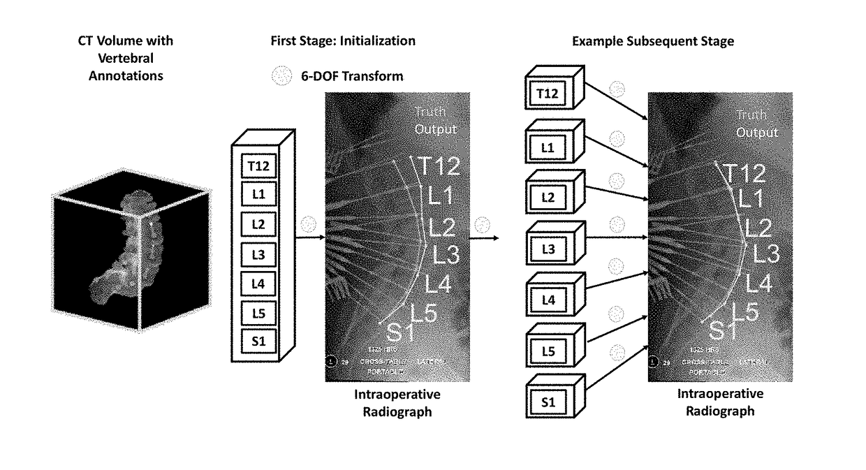
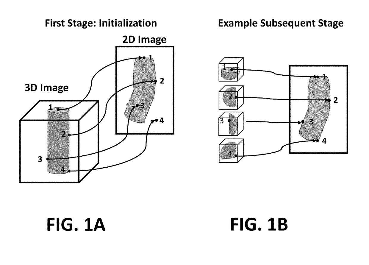
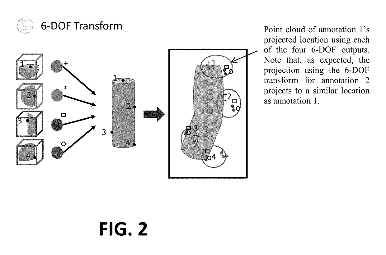
This patent describes a method and system for registering 3D image data to 2D image data. The method includes identifying predefined annotations in the 3D image data and performing locally rigid registrations in a hierarchical manner to map information from the 3D image to the 2D image. The method also includes dividing the image into divided regions according to the annotations and determining the registration for each divided region using a volumetric masking method. The system includes an image scanner for obtaining 3D image data, a non-transitory computer readable medium for executing the method, and a display for displaying the registered information from the 3D image data to the 2D image data. The technical effect of this patent is to improve the accuracy and precision of registering 3D image data to 2D image data, which can be useful in various fields such as medical diagnosis and surgical procedures.

Problems solved by technology

Existing methods for image-intensity-based 3D-2D annotation mapping have used a rigid transformation and can be limited by deformation in anatomy.
This results in a deformation of anatomy, including the structures of interest in surgery (e.g., the spinal vertebrae).
Deformable image registration could improve accuracy in these scenarios, but such methods are susceptible to local optima and often fail due to a large number of parameters being optimized and an inherent degeneracy between magnification and object enlargement.
Piece-wise rigid registration methods exist in feature-based registration to account for these deformations; however, segmentations or shape models need to be extracted from the 3D image to perform the registration, creating additional work in planning, introducing sources of error in segmentation, and often disregarding potentially relevant image intensity information.

Method used


Image

  • Method for deformable 3d-2d registration using multiple locally rigid registrations
  • Method for deformable 3d-2d registration using multiple locally rigid registrations
  • Method for deformable 3d-2d registration using multiple locally rigid registrations

Examples


Embodiment Construction

[0023]The presently disclosed subject matter now will be described more fully hereinafter with reference to the accompanying Drawings, in which some, but not all embodiments of the inventions are shown. Like numbers refer to like elements throughout. The presently disclosed subject matter may be embodied in many different forms and should not be construed as limited to the embodiments set forth herein; rather, these embodiments are provided so that this disclosure will satisfy applicable legal requirements. Indeed, many modifications and other embodiments of the presently disclosed subject matter set forth herein will come to mind to one skilled in the art to which the presently disclosed subject matter pertains having the benefit of the teachings presented in the foregoing descriptions and the associated Drawings. Therefore, it is to be understood that the presently disclosed subject matter is not to be limited to the specific embodiments disclosed and that modifications and other ...


PUM


Abstract

An embodiment in accordance with the present invention provides a method for 3D-2D registration (for example, registration of a 3D CT image to a 2D radiograph) that permits deformable motion between structures defined in the 3D image based on a series of locally rigid transformations. This invention utilizes predefined annotations in 3D images (e.g., the location of anatomical features of interest) to perform multiple locally rigid registrations that yield improved accuracy in aligning structures that have undergone deformation between the acquisition of the 3D and 2D images (e.g., a preoperative CT compared to an intraoperative radiograph). The 3D image is divided into subregions that are masked according to the annotations, and the registration is computed simultaneously for each divided region by incorporating a volumetric masking method within the 3D-2D registration process.

Description

CROSS REFERENCE TO RELATED APPLICATIONS[0001]This application claims the benefit of U.S. Provisional Patent Application No. 62 / 269,371 filed December 18, which is incorporated by reference herein, in its entirety.FIELD OF THE INVENTION[0002]The present invention relates generally to imaging. More particularly the present invention relates to a method for deformable registration of 3D image information with a single 2D image (referred to as 3D-2D registration) using multiple locally rigid registrations.BACKGROUND OF THE INVENTION[0003]3D preoperative imaging (e.g., CT, MRI, PET) provides the basis for many forms of surgical planning and intraoperative guidance. During the surgical planning stage, clinicians may define geometric annotations (points, contours, shapes, etc.) in the preoperative 3D images, such as defining a point on an anatomical structure of interest, outlining relevant anatomical structures, and identifying the desired placement / trajectory of surgical hardware. These ...

Claims


Application Information

Patent Timeline
IPC IPC(8): G06T7/33G06T7/37
CPCG06T7/337G06T7/37G06T2207/10088G06T2207/20221G06T2207/10116G06T2207/20048G06T2207/10081G06T2207/10104G06T2207/30012G06T7/33
Inventor KETCHA, MICHAELDESILVA, WATHUDRAGE THARINDUUNERI, ALIWOLINSKY, JEAN-PAULSIEWERDSEN, JEFFREY H.
Owner THE JOHN HOPKINS UNIV SCHOOL OF MEDICINE
Learn More