Camera pose determining method and device

A determination method and camera technology, applied in image data processing, instrumentation, calculation, etc., can solve the problems of easy tracking error, instability, and high power consumption

Active Publication Date: 2018-05-11
北京墨土科技有限公司
View PDF8 Cites 13 Cited by
  • Summary
  • Abstract
  • Description
  • Claims
  • Application Information

AI Technical Summary

Problems solved by technology

[0005] For OIT: it is expensive and difficult to deploy; it is only 3 degrees of freedom tracking, which can only track the translation position, and the rotation direction needs to calculate the rotation direction of the entire rigid body by capturing multiple positions on a rigid body, so mark Large size, poor attitude accuracy, easy to track errors in the case of multiple people and multiple points; in addition, because it is not calculated locally at the receiving end, it needs to calculate the position and then transmit it to the receiving end wirelessly, so wireless transmission is easy to introduce delay
[0006]

Method used


Image

  • Camera pose determining method and device
  • Camera pose determining method and device
  • Camera pose determining method and device

Examples


Embodiment Construction

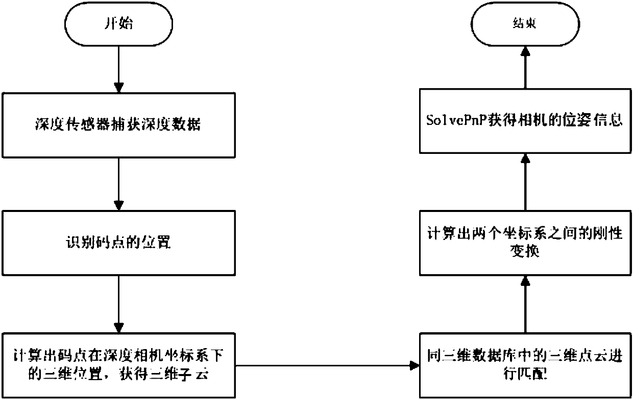
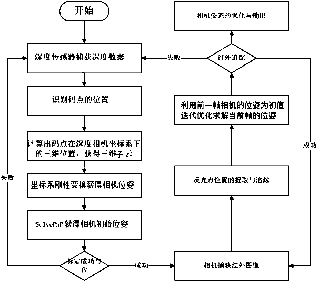
[0095] The technical solutions of the present invention will be further specifically described below through the embodiments and in conjunction with the accompanying drawings. In the specification, the same or similar reference numerals designate the same or similar components. The following description of the embodiments of the present invention with reference to the accompanying drawings is intended to explain the general inventive concept of the present invention, but should not be construed as a limitation of the present invention.

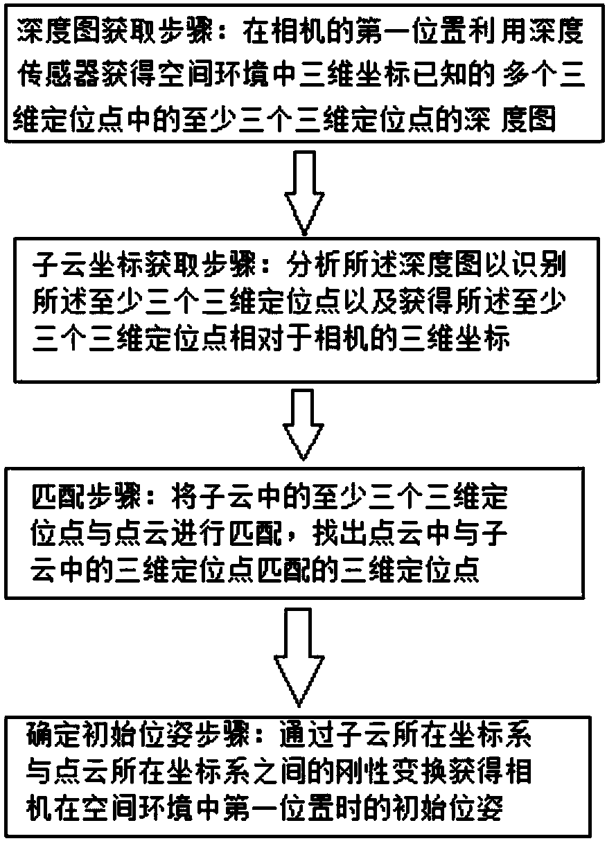
[0096] In the present invention, the markers can be randomly pasted in the environment in advance, and the deployment density should ensure that at least 4 markers can appear in the field of view of the depth camera (preferably pasted on a fixed object in the environment, such as a wall, more preferably pasted on a on the ceiling). It is necessary to measure the 3D position or 3D coordinates of each marker, and then save the coordinate data a...


PUM


Abstract

The invention relates to a camera pose determining method. The method comprises a depth map obtaining step in which in a first position of a camera, a depth sensor is used to obtain a depth map of atleast three of 3D positioning points with known 3D coordinates in a space environment, the 3D positioning points form code points in the depth map, and the 3D positioning points form a point cloud inthe space environment; a sub cloud coordinate obtaining step in which the depth map is analyzed to identify the at least three 3D positioning points and obtain 3D coordinates, relative to the camera,of the at least three 3D positioning points, and the at least three 3D positioning points form a sub cloud; a matching step in which the at least three 3D positioning points in the sub cloud matches the point cloud to search the point cloud for 3D positioning points that match 3D positioning points in the sub cloud; and an initial pose determining step in which an initial pose of the camera in thefirst position in the space environment is obtained via rigid transformation between a coordinate system of the sub cloud and a coordinate system of the point cloud. The invention also relates to a camera pose determining device.

Description

technical field [0001] The invention relates to the field of positioning and tracking, in particular to a camera pose determining method and a camera pose determining device. Background technique [0002] Tracking system is widely used in augmented reality (Augmented Reality, AR) / virtual reality (Virtual Reality, VR) human-computer interaction and robot navigation, and is one of the core and bottom-level technologies. In the field of human-computer interaction such as AR / VR, positioning and posture determination are a very critical part, which is the basis of human-machine interaction. Human-computer interaction requires high precision (such as reaching the millimeter level and angular classification) and high real-time requirements (such as 10 milliseconds) for positioning and posture determination (that is, determining the pose). [0003] Motion tracking systems can be divided into two types of technologies: Outside-In Tracking (OIT) and Inside-out Tracking (IOT). The ob...

Claims


Application Information

Patent Timeline
IPC IPC(8): G06T7/73G06T7/55
CPCG06T2207/30244G06T2207/10048G06T2207/10028
Inventor 周恺弟王学运潘成伟
Owner 北京墨土科技有限公司
Why Eureka
Try Eureka