Method and apparatus for extracting and using path shading coherence in a ray tracing architecture

a path shading and architecture technology, applied in the field of apparatus and methods for extracting path shading coherence in a ray tracing architecture, can solve the problems of degrading shading coherence, affecting the accuracy of lighting simulation, and requiring higher computational costs

Active Publication Date: 2017-06-22
INTEL CORP
View PDF7 Cites 38 Cited by
  • Summary
  • Abstract
  • Description
  • Claims
  • Application Information

AI Technical Summary

Problems solved by technology

However, with the constant demand for increased visual fidelity, many studios and production companies are now switching to ray tracing architectures, where accurate lighting simulations can be performed, yet at a higher computational cost.
This ray distribution quickly leads to degraded shading coherence after just a few bounces.

Method used


Image

  • Method and apparatus for extracting and using path shading coherence in a ray tracing architecture
  • Method and apparatus for extracting and using path shading coherence in a ray tracing architecture
  • Method and apparatus for extracting and using path shading coherence in a ray tracing architecture

Examples


Embodiment Construction

[0025]In the following description, for the purposes of explanation, numerous specific details are set forth in order to provide a thorough understanding of the embodiments of the invention described below. It will be apparent, however, to one skilled in the art that the embodiments of the invention may be practiced without some of these specific details. In other instances, well-known structures and devices are shown in block diagram form to avoid obscuring the underlying principles of the embodiments of the invention.

Exemplary Graphics Processor Architectures and Data Types

[0026]System Overview

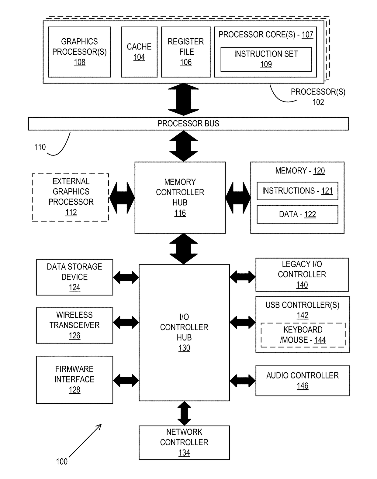
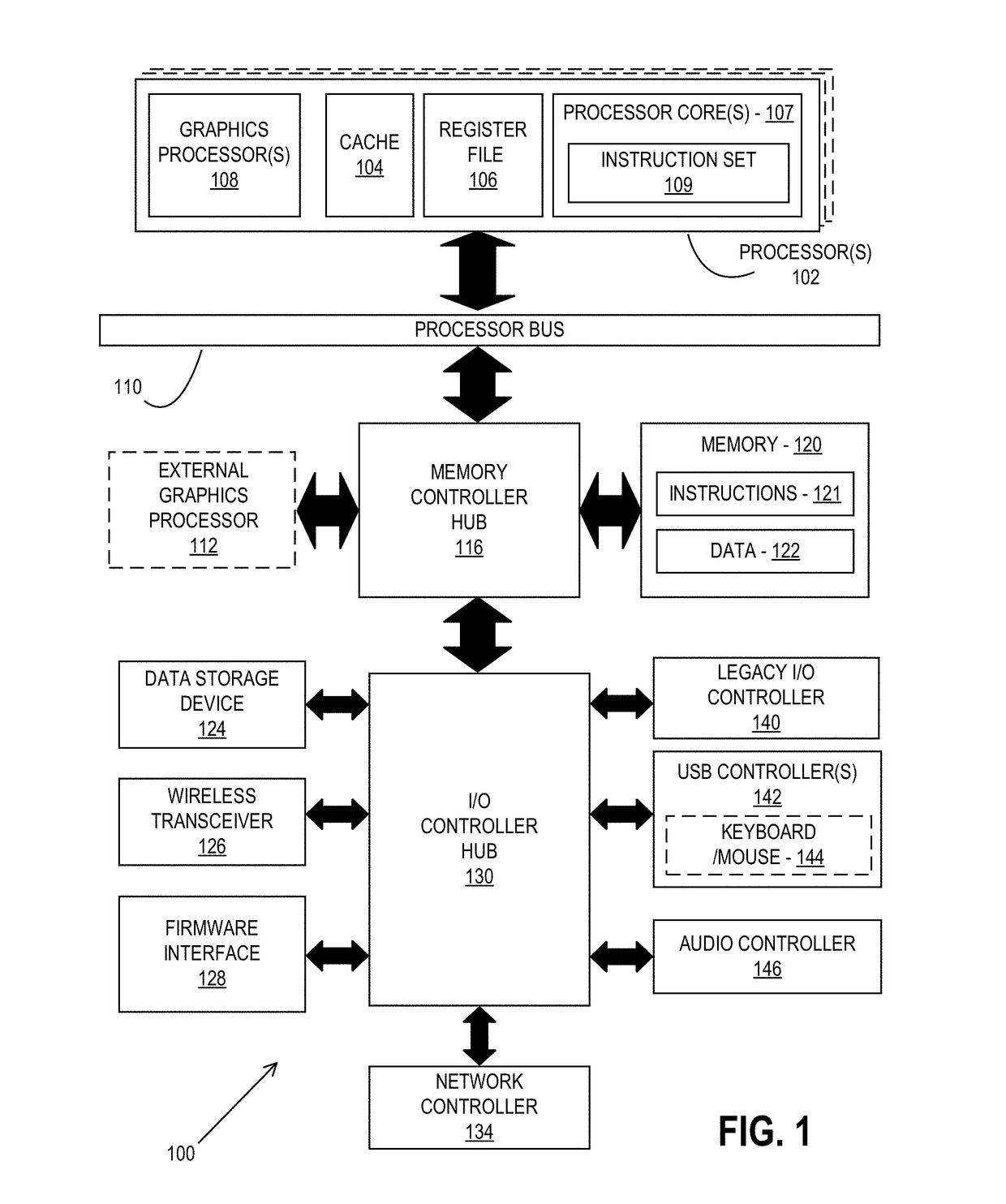
[0027]FIG. 1 is a block diagram of a processing system 100, according to an embodiment. In various embodiments the system 100 includes one or more processors 102 and one or more graphics processors 108, and may be a single processor desktop system, a multiprocessor workstation system, or a server system having a large number of processors 102 or processor cores 107. In on embodiment, the sys...


PUM


Abstract

An apparatus and method for extracting and using path shading coherence in a ray tracing architecture. For example, one embodiment of a graphics processing apparatus comprises: ray generation logic to generate a ray stream from one or more image tiles; ray sorting logic to sort the rays within the ray stream based on a material identifier (ID) associated with each of the rays to generate a sorted ray stream; and one or more shaders to perform shading operations on rays within the sorted ray stream in an order in which the rays are sorted within the sorted ray stream.

Description

BACKGROUND[0001]Field of the Invention[0002]This invention relates generally to the field of computer processors. More particularly, the invention relates to an apparatus and method for extracting path shading coherence in a ray tracing architecture.[0003]Description of the Related Art[0004]Ray tracing is a graphics processing technique for generating an image by traversing the path of each light ray through pixels in an image plane and simulating the effects of its incidence upon different objects. Following traversal calculations, each ray is typically tested for intersection with some subset of the objects in the scene. Once the nearest object has been identified, the incoming light at the point of intersection is estimated, the material properties of the object are determined, and this information is used to calculate the final color of the pixel.[0005]Production rendering for visual effects has recently undergone a paradigm shift towards ray tracing architectures. Traditionally...

Claims


Application Information

Patent Timeline
Patent Type & Authority Applications(United States)
IPC IPC(8): G06T15/80G06T15/06
CPCG06T15/06G06T15/80G06T1/20G06T15/50G06T15/60
Inventor AFRA, ATTILA T.MUNKBERG, CARL J.
Owner INTEL CORP
Why Eureka
Try Eureka