
Echo canceller device

a canceller and filter technology, applied in the field of echo canceller devices, can solve the problems of increasing the difficulty of acquiring the filter coefficient h(k), requiring a large modification amount of the filter coefficient h(, and taking time for convergence, so as to secure the elimination of echo signals, and stable echo cancelling performance

Inactive Publication Date: 2017-06-22
AMENITY RES INST
View PDF9 Cites 8 Cited by
  • Summary
  • Abstract
  • Description
  • Claims
  • Application Information

AI Technical Summary

Benefits of technology

This patent describes a device that cancels out echo signals caused by a speaker being captured by a microphone. The device uses a delaying mechanism to create an echo signal from the speaker's input signal and then filters it using a trained filter to cancel out the echo. The device also has a noise suppression unit to handle large amounts of noise. These filters are generated based on the received signal and help to ensure a high-quality voice signal is captured. Additionally, the device has an internal feedback unit that allows for stable echo cancelling even when the received signal is not optimal. Overall, this device achieves efficient and effective echo cancellation in various situations.

Problems solved by technology

(2) The larger the noise n(k) becomes, the more difficult it becomes to acquire the filter coefficient h(k) that is the estimated value of the impulse response h′(k).
This means that there is a large change in the impulse response h′(k), so that it requires a large modification amount in the filter coefficient h(k) and it takes time for the convergence thereof.
Therefore, the echo cancel performance is greatly deteriorated during that time.

Method used


Image

  • Echo canceller device
  • Echo canceller device
  • Echo canceller device

Examples


first embodiment

(First Embodiment)

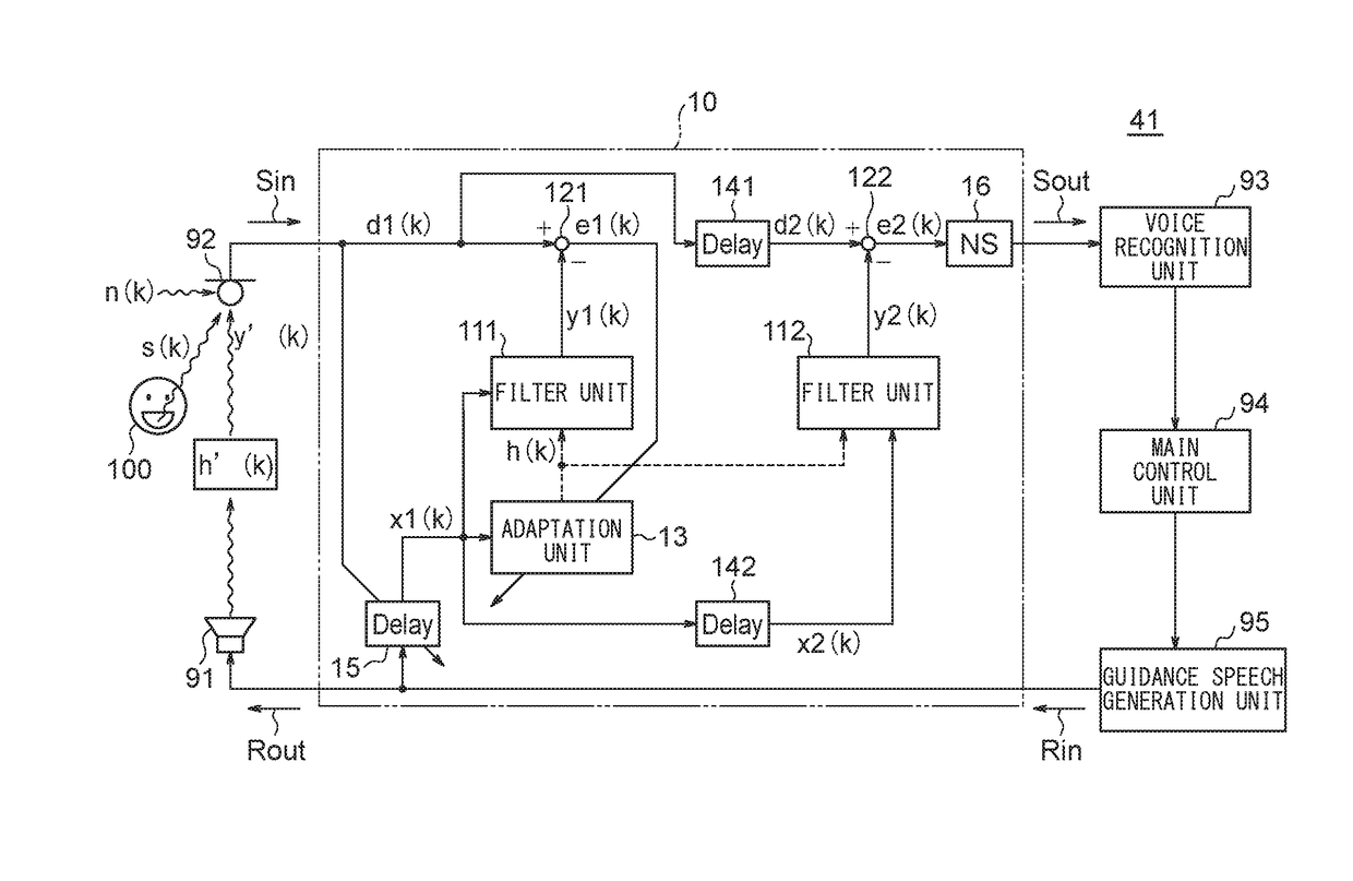
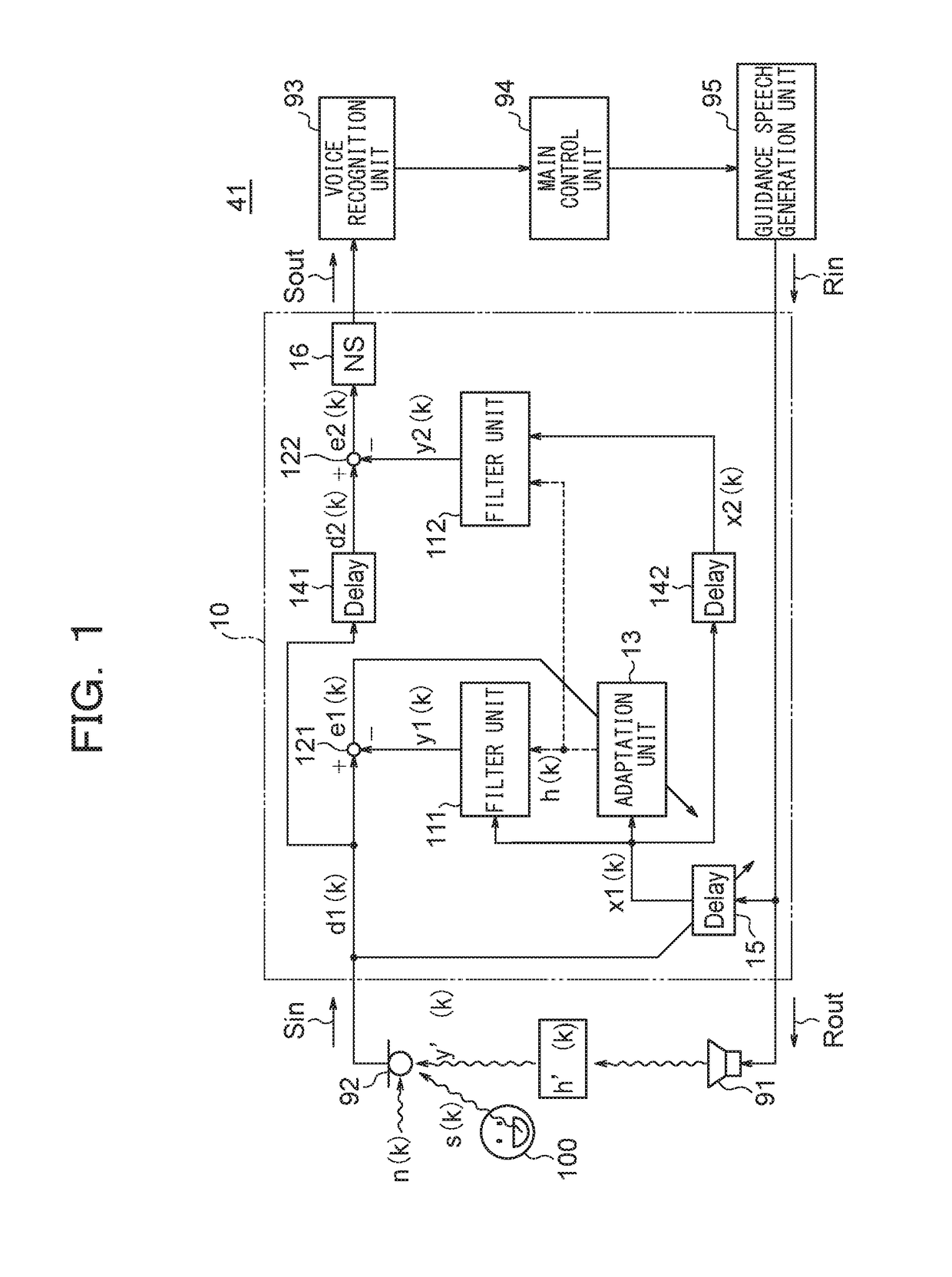
[0111]10 Echo canceller device[0112]111 First filter unit[0113]112 Second filter unit[0114]121 First subtraction unit[0115]122 Second subtraction unit[0116]13 Adaptation unit[0117]141 First delaying unit[0118]142 Second delaying unit[0119]15 Delay adjustment unit[0120]16 Noise suppression unit[0121]41 Navigation system[0122]91 Speaker[0123]92 Microphone[0124]93 Voice recognition unit[0125]94 Main control unit[0126]9.5 Guidance speech generation unit[0127]100 User[0128]y′(k) Echo signal[0129]x1(k) First input signal[0130]x2(k) Second input signal[0131]d1(k) First objective signal[0132]d2(k) Second objective signal[0133]h(k) Filter coefficient[0134]y1(k) First output signal[0135]y2(k) Second output signal[0136]e1(k) First error signal[0137]e2(k) Second error signal[0138]s(k) Speaker signal[0139]n(k) Noise[0140]h′(k) Impulse response[0141]Sin, Sout Transmission signal[0142]Rin, Rout Reception signal

second embodiment

(Second Embodiment)

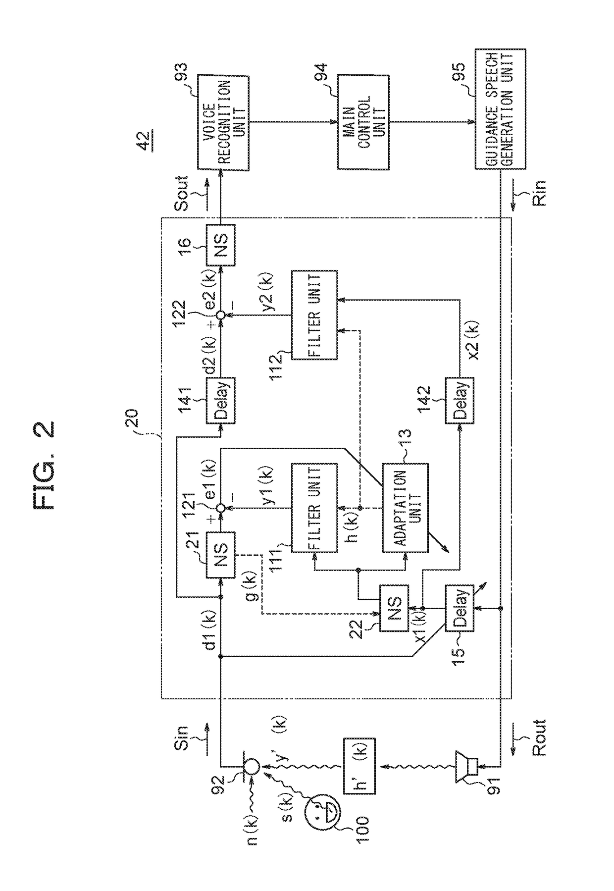
[0143]20 Echo canceller device[0144]21 First noise suppression unit[0145]22 Second noise suppression unit[0146]42 Navigation system

third embodiment

(Third Embodiment)

[0147]30 Echo canceller device[0148]31 Internal feedback unit[0149]32 Amplifier[0150]33 Adder[0151]43 Navigation system

(Related Technique 1)

[0152]80 Echo canceller device[0153]81 Filter unit[0154]82 Subtraction unit[0155]83 Adaptation unit[0156]85 Delay adjustment unit[0157]86 Noise suppression unit[0158]90 Navigation system[0159]x(k) Input signal[0160]d(k) Objective signal[0161]y(k) Output signal[0162]e(k) Error signal


PUM


Abstract

An echo canceller device is provided with a first filter unit that generates a first output signal y1(k) by filtering a first input signal x1(k) with a filter coefficient h(k), an adaptation unit that modifies the filter coefficient h(k) on the basis of an adaptation algorithm so that a first error signal e1(k) becomes small, a first delaying unit that delays a first objective signal d1(k) by a certain time period τ and outputs the signal as a second objective signal d2(k), a second delaying unit that delays the first input signal x1(k) by the certain time period τ and outputs the signal as a second input signal x2(k), and a second filter unit that generates a second output signal y2(k) by filtering the second input signal x2(k) by the filter coefficient h(k) modified by the adaptation unit.

Description

TECHNICAL FIELD[0001]The present invention relates to an echo canceller device that eliminates echo signals generated when a voice reproduced from a speaker is captured by a microphone.BACKGROUND ART[0002]Recently, cases of using voice recognition as a means for operating apparatuses have been increasing due to the improvement in the recognition performance. In the field of automobiles in particular, operations with voice recognition without using hands while driving has drawn an attention in view of safety.[0003]In a car navigation system, for example, various kinds of information such as map information, various kinds of accompanying information thereof, and entertainment information are collected, and operations of apparatuses based on such information are executed by voice recognition. That is, the car navigation system controls the related apparatuses while conversing with the user including the driver. In such case, the navigation system takes in charge of the main function of...

Claims


Application Information

Patent Timeline
Patent Type & Authority Applications(United States)
IPC IPC(8): G10L21/0232G10L15/22H04R3/02G10L13/00
CPCG10L21/0232G10L13/00G10L2021/02163H04R3/02G10L2021/02082G10L15/22H04B3/232H04M9/082H04R3/04G10L21/0208
Inventor MISAWA, EIJIYAGI, TOSHIOSHIBATA, YASUMASATOYOZUMI, HIROYUKIARAI, KIYOTSUGUSATOH, KATSUAKI
Owner AMENITY RES INST
Learn More