Supercharge Your Innovation With Domain-Expert AI Agents!

Boat Trailer & Method for Securing Boat Thereto

Inactive Publication Date: 2017-06-29
RICE BROOKS
View PDF22 Cites 2 Cited by
  • Summary
  • Abstract
  • Description
  • Claims
  • Application Information

AI Technical Summary

Benefits of technology

The invention is a boat trailer with a special pivot-roller mechanism that prevents the boat from sliding sideways or backwards during transport. The mechanism uses the weight of the boat to secure it in place using longitudinal bunk supports and a stern capture flange with rollers. This patent also describes a method for securing a boat using the pivot-roller mechanism. The technical effect of this invention is improved safety and stability for transporting boats.

Problems solved by technology

There are a number of problems associated with existing means of securing a boat to its trailer.
First, over time some strapping means become worn.
Second, these strapping means are not suitable for all types of boats and trailers; were a boat to lack a suitable anchor point on the stern the user would lack the point to which a tie-down ratcheting strap could fasten.
Third, users may neglect to use the tie-down ratcheting straps properly (or at all).
When this occurs, the boat may bounce off the trailer or slide side-to-side while traveling down the road thereby creating a very dangerous condition.
This makes loading easier; however, none of the currently available devices, bunks or rollers, serve the dual purpose of stabilizing the boat and securing the boat to the boat trailer.

Method used


Image

  • Boat Trailer & Method for Securing Boat Thereto
  • Boat Trailer & Method for Securing Boat Thereto
  • Boat Trailer & Method for Securing Boat Thereto

Examples


first preferred embodiment

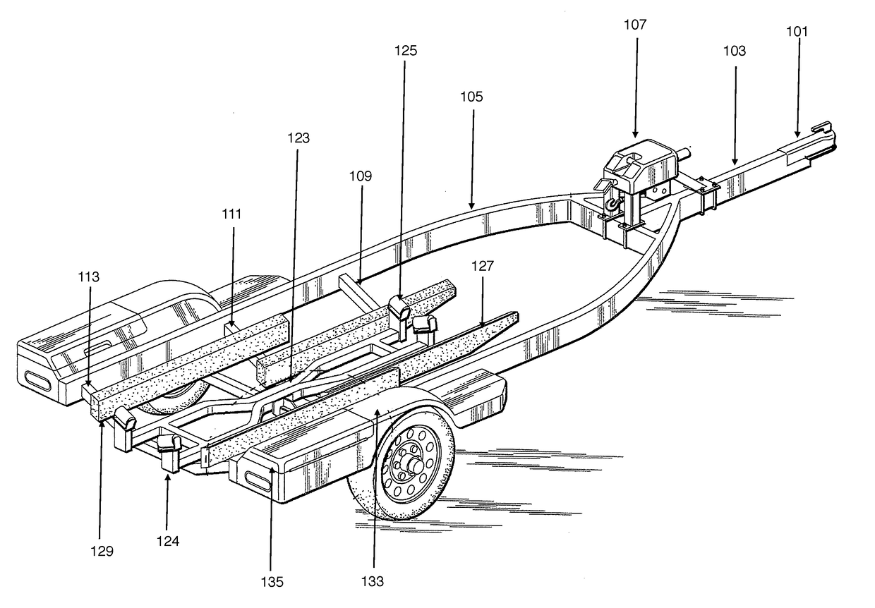
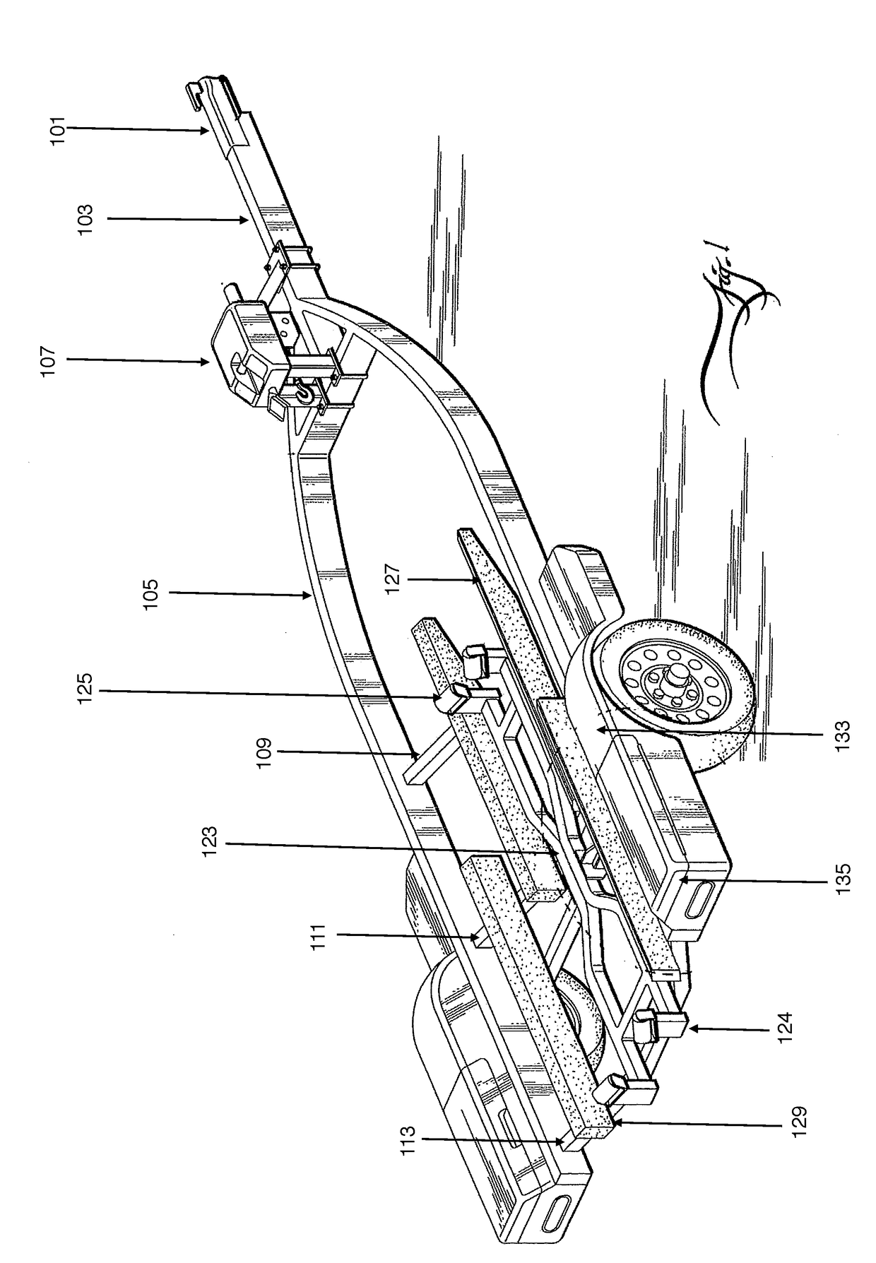
[0036]In this first preferred embodiment, depicted in FIG. 1, a unique boat trailer is comprised of a towing coupler assembly 101, a tongue 103, a frame 105, longitudinal bunks (127, 129), cross members (109, 111, 113), a wheel and axle assembly 131, and fenders 133. Additionally, the trailer contains a novel pivoting roller mechanism assembly 115 having a unique stern flange 124, which serves to secure and prevent the boat from sliding off of the rear of the boat trailer. As shown in FIG. 1, the stern flange 124 preferentially incorporates rollers in this first preferred embodiment.

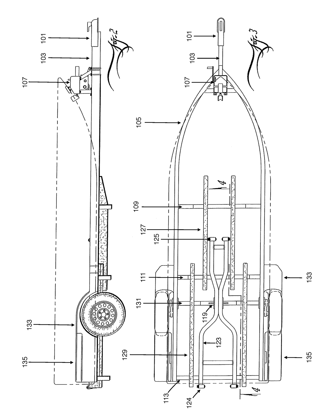
[0037]The trailer has a front (bow) and a back (stern) with port (left) and starboard (right) sides. As shown in FIG. 3, the tongue 103 and frame 105 combine to form a skeleton structure to which the other elements of the trailer attach. The tongue 103 extends transversely along the longitudinal centerline of the frame 105 and connects to the frame 105 at the bow end of the trailer, extending to the ster...

second preferred embodiment

[0047]As shown in FIGS. 6-9, this second preferred embodiment discloses a method of securing a boat to the trailer wherein the boat trailer incorporates a mechanism such as a pivot roller mechanism assembly 115, as disclosed in the first preferred embodiment.

[0048]Starting from a first position whereby the trailer is partially submerged into the water, the user begins to navigate a boat onto the trailer. As the user navigates the boat into a second position upon the trailer, the boat hull actuates the front rollers 125 of the pivot roller mechanism 123, which assist in the proper seating of the boat hull into proper alignment on the boat trailer. As the boat is navigated into a final resting position, the boat stern moves forward beyond the stern capture flange 124. The weight of the boat applies pressure to the pivot roller mechanism 123 thereby actuating the stern capture flange 124 into a final position that captures the boat hull. This process secures the boat on the trailer. In...


PUM


Abstract

Disclosed is a boat trailer incorporating a pivoting mechanism wherein a stern capture flange serves to secure the stern of the boat so as to prevent the boat from sliding off of the rear of the boat trailer. Specifically, the invention utilizes the weight of the boat itself to trigger the fulcrum action of the pivoting roller mechanism, wherein the boat is mechanically seated in place via the inward contact face of the stern capture flange. Also disclosed is a method for securing a boat to a trailer having a pivoting roller mechanism.

Description

GOVERNMENTAL RIGHTS[0001]None.BACKGROUND OF THE INVENTION[0002]The present invention relates to boat trailers and constitutes a novel pivot actuating mechanism with flange for securing a boat to a boat trailer.[0003]There are commercially available methods for securing a boat to a trailer. One method is to first secure the bow of the boat to the boat trailer using a winch mechanism from which a strap and hook extend to secure the bow of the boat to the trailer. As part of this method, a user then secures the stern of the boat to the rear of the trailer using tie-down ratcheting straps. Typically there are corresponding anchor points on both the stern of the boat and trailer.[0004]There are a number of problems associated with existing means of securing a boat to its trailer. First, over time some strapping means become worn. This requires the user to replace the strapping means in order to ensure that the boat is securely attached to the boat trailer. Second, these strapping means a...

Claims


Application Information

Patent Timeline
IPC IPC(8): B60P3/10
CPCB60P3/1058B60P3/1066
Inventor RICE, BROOKS
Owner RICE BROOKS
Features
  • R&D
  • Intellectual Property
  • Life Sciences
  • Materials
  • Tech Scout
  • Unparalleled Data Quality
  • Higher Quality Content
  • 60% Fewer Hallucinations
Learn More