Frac flow-back control and/or monitoring system and methods

a flow-back control and monitoring system technology, applied in the field of fluid flow control systems and methods, can solve problems such as decrepit production and decrepit production

Active Publication Date: 2017-07-06
SPM OIL & GAS PC LLC
View PDF4 Cites 105 Cited by
  • Summary
  • Abstract
  • Description
  • Claims
  • Application Information

AI Technical Summary

Benefits of technology

[0031]In an exemplary embodiment, the first valve is a first electric-actuated choke having an open/closed position; wherein the electronic controller is adapted to transmit a first control output to the first electric-actuated choke, the first control output being based on at least the first portion of the measurement data; and wherein the first electric-actuated choke is adapted to adjust its open/closed position, based on the first control output, to thereby actively control the pressure of the wellbore of which the wellhead is the surface termination.
[0032]In

Problems solved by technology

For example, if the wellbore fluid flow is too fast (i.e., the wellbore fluid volumetric flow rate or velocity is too high), the wellbore may collapse, decreasing production

Method used


Image

  • Frac flow-back control and/or monitoring system and methods
  • Frac flow-back control and/or monitoring system and methods
  • Frac flow-back control and/or monitoring system and methods

Examples


Embodiment Construction

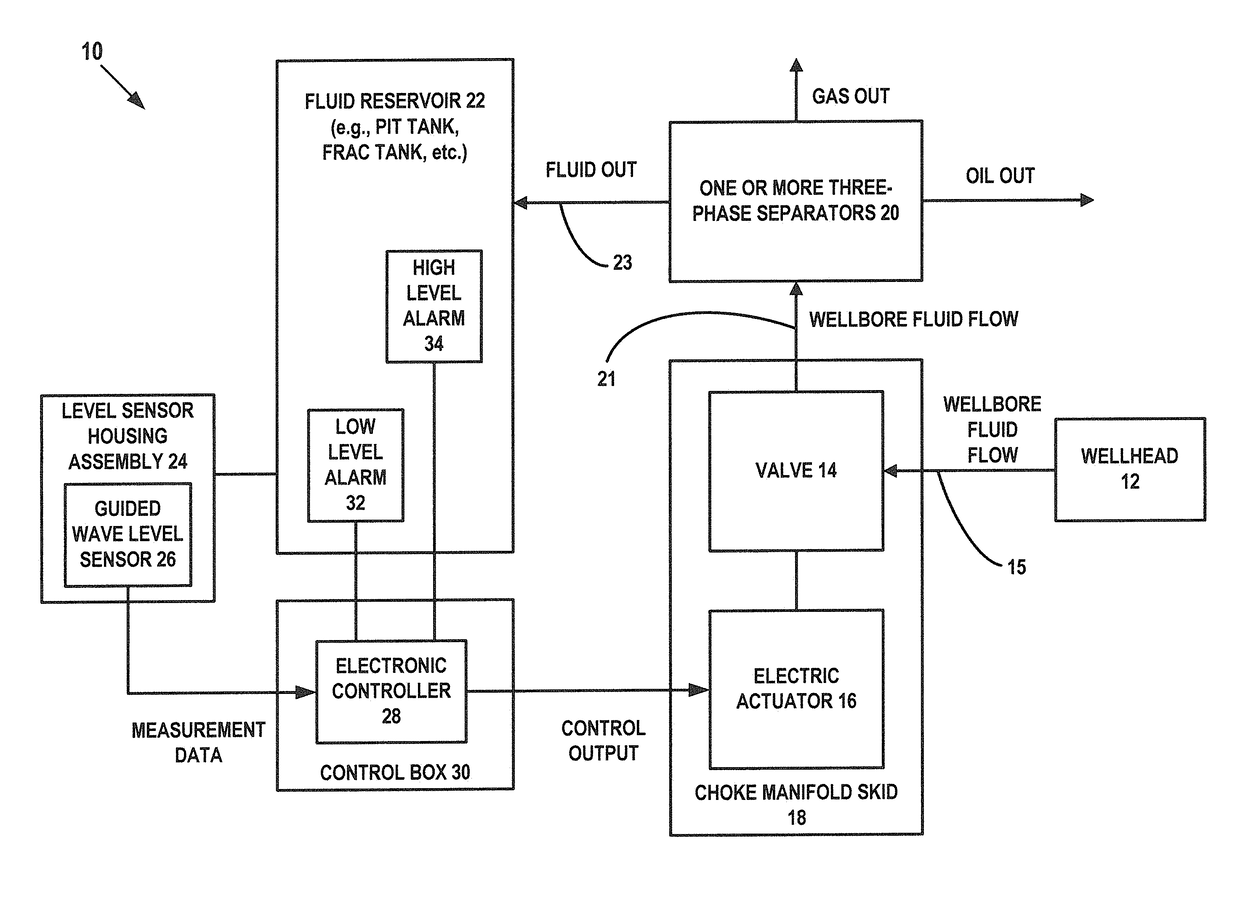
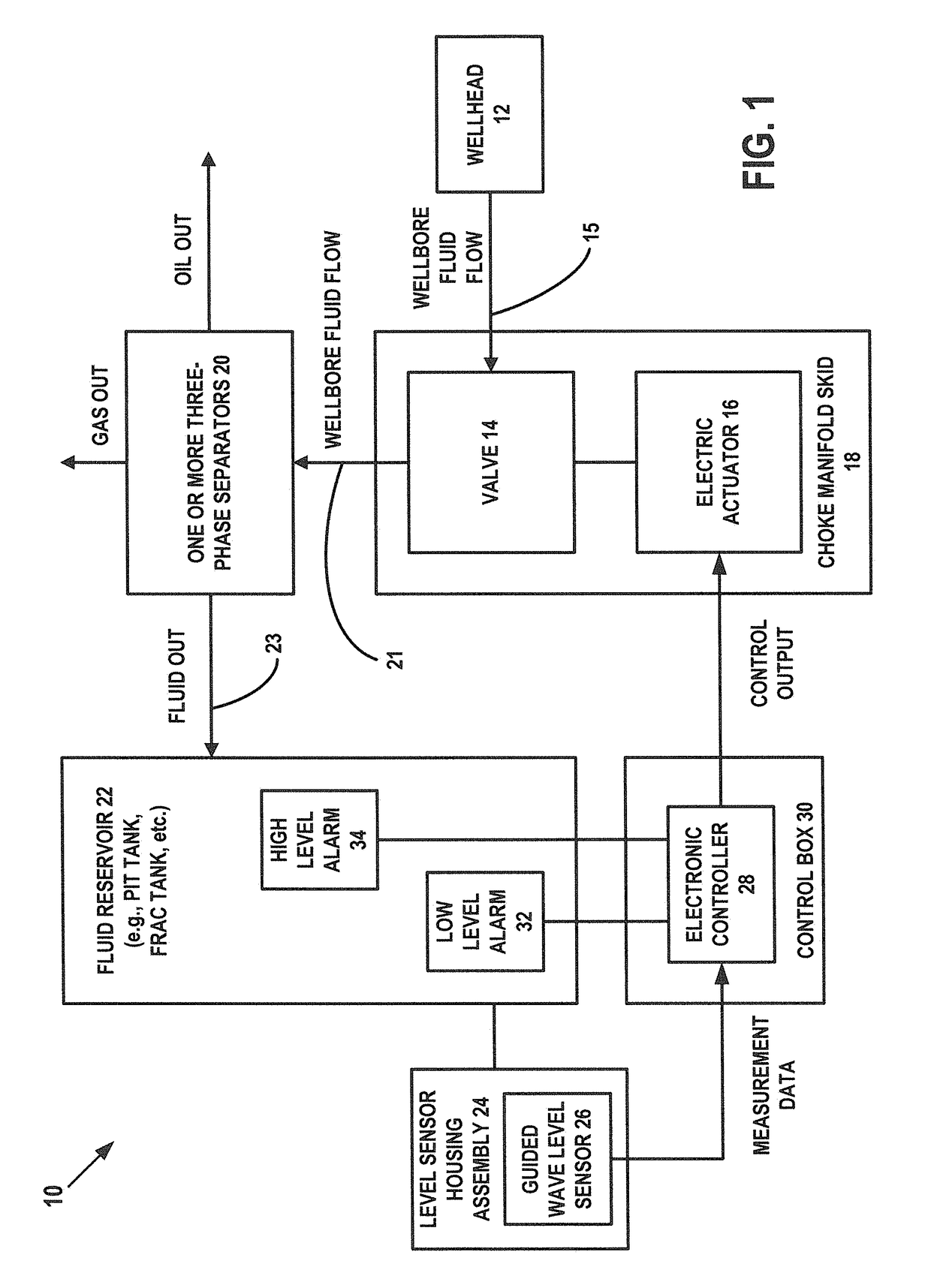
[0093]In an exemplary embodiment, as illustrated in FIG. 1, a system is generally referred to by the reference numeral 10 and includes a wellhead 12 out of which wellbore fluid is adapted to flow. The wellhead 12 is the surface termination of an oil and gas wellbore that extends through one or more subterranean formations. A valve 14 is in fluid communication with the wellhead 12 via at least a fluid line 15. An electric actuator 16 is operably coupled to the valve 14. The valve 14 and the electric actuator 16 operably coupled thereto are associated with a choke manifold skid 18; in several exemplary embodiments, the valve 14 and the electric actuator 16 are associated with the choke manifold skid 18 by being mounted on, and / or a part of, the choke manifold skid 18.

[0094]One or more three-phase separators 20 are in fluid communication with the valve 14 via at least a fluid line 21. A fluid reservoir 22 is in fluid communication with the one or more three-phase separators 20 via at l...


PUM


Abstract

According to one aspect, a system is adapted to actively control one or more operating parameters associated with: a wellbore extending in a subterranean formation, and/or wellbore fluid flowing out of the wellbore via a wellhead. The system includes one or more sensors; an electronic controller adapted to receive from the one or more sensors measurement data; and a valve through which the wellbore fluid is adapted to flow. The valve is adapted to be in communication with the electronic controller. The active control of the at least one of the one or more operating parameters is adapted to facilitate: maintenance of the integrity of the wellbore, and/or enhancement of oil and/or gas production out of the wellbore. In one embodiment, the wellbore fluid flow is frac flow-back. In another aspect, a system is adapted to monitor vent gas separated from wellbore fluid flowing out a wellhead.

Description

CROSS-REFERENCE TO RELATED APPLICATIONS[0001]This patent application claims priority to, and the benefit of the filing date of, U.S. Application No. 62 / 273,568, filed Dec. 31, 2015, the entire disclosure of which is hereby incorporated herein by reference.[0002]This patent application claims priority to, and the benefit of the filing date of, U.S. Application No. 62 / 347,872, filed Jun. 9, 2016, the entire disclosure of which is hereby incorporated herein by reference.[0003]This patent application is related to the following patent applications: (1) U.S. Application No. 62 / 089,913, filed Dec. 10, 2014; (2) U.S. Application No. 62 / 173,633, filed Jun. 10, 2015; (3) U.S. Application No. 62 / 180,735, filed Jun. 17, 2015; (4) U.S. application Ser. No. 14 / 963,839, filed Dec. 9, 2015; (5) International Application No. PCT / US2015 / 064625, filed Dec. 9, 2015, (6) International Application No. PCT / US2015 / 064618, filed Dec. 9, 2015; (7) U.S. Application No. 62 / 273,568, filed Dec. 31, 2015; (8) U....

Claims


Application Information

Patent Timeline
IPC IPC(8): E21B41/00E21B47/04E21B47/06E21B34/06E21B43/26
CPCE21B41/0092E21B34/066E21B47/042E21B47/06E21B47/065E21B43/26
Inventor JOHNS, ROGERFOLMAR, STEPHENGREEN, MATTHEW B.AKTAS, LEVENTLONG, TIMOTHYHERSCHE, RON
Owner SPM OIL & GAS PC LLC
Why Eureka
Try Eureka