
Repeater and signal attenuation method thereof

Active Publication Date: 2017-07-06
SOLID
View PDF6 Cites 2 Cited by
  • Summary
  • Abstract
  • Description
  • Claims
  • Application Information

AI Technical Summary

Benefits of technology

The patent is about a way to prevent signals from being too powerful when they reach a repeater. This is important because too much power can damage or limit the performance of the repeater. The inventor developed a method to efficiently calculate peak power and use that information to adjust the signal to the proper strength. This technology can improve the overall quality and safety of signals transmitted through repeaters.

Problems solved by technology

However, the repeater may not operate properly due to excessive power of signals received through an antenna of the repeater.

Method used


Image

  • Repeater and signal attenuation method thereof
  • Repeater and signal attenuation method thereof
  • Repeater and signal attenuation method thereof

Examples


Embodiment Construction

[0028]The inventive concept may be variously modified and have various example embodiments, so that specific example embodiments will be illustrated in the drawings and described in the detailed description. However, this does not limit the inventive concept to specific example embodiments, and it should be understood that the inventive concept covers all the modifications, equivalents and replacements included within the idea and technical scope of the inventive concept.

[0029]In describing the inventive concept, in the following description, a detailed explanation of known related technologies may be omitted to avoid unnecessarily obscuring the subject matter of the inventive concept. In addition, numeral figures (for example, 1, 2, and the like) used during describing the specification are just identification symbols for distinguishing one element from another element.

[0030]Further, in the specification, if it is described that one component is “connected” or “accesses” the other ...


PUM


Abstract

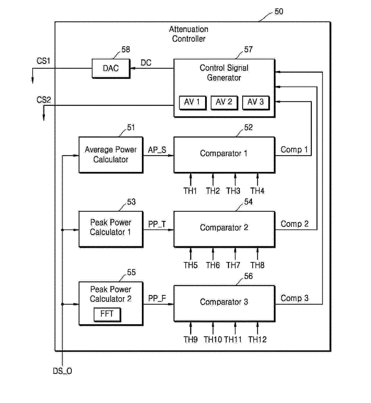
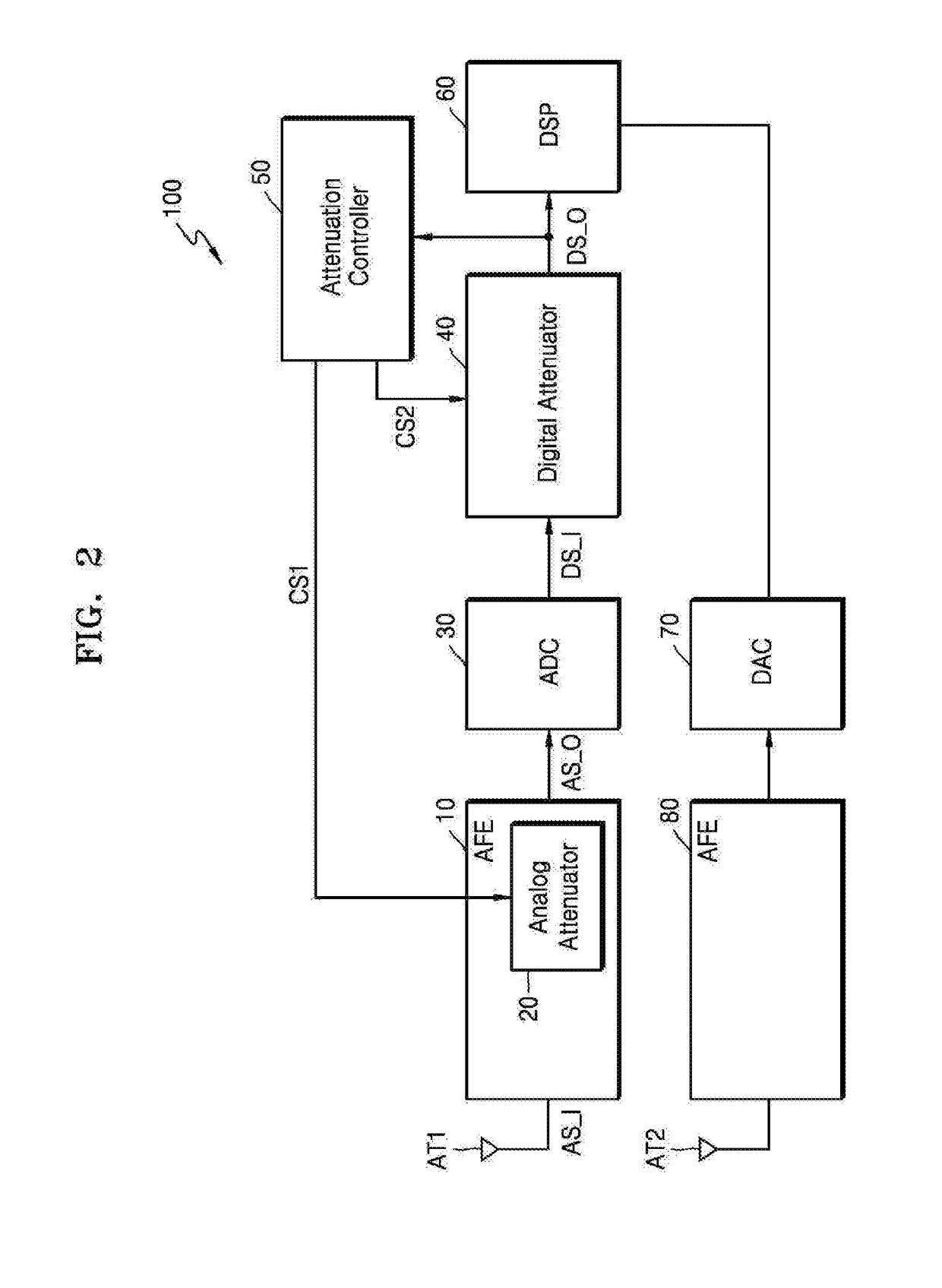
A repeater including an analog attenuator configured to attenuate an analog signal in response to a first control signal; an analog to digital converter (ADC) configured to convert the attenuated analog signal into a digital signal; a digital attenuator configured to attenuate the digital signal in response to a second control signal; and an attenuation controller configured to calculate average power and peak power of the attenuated digital signal, determine an attenuation value for each value of the calculated average power and peak power, and generate at least one of the first and second control signals based on the determined attenuation values.

Description

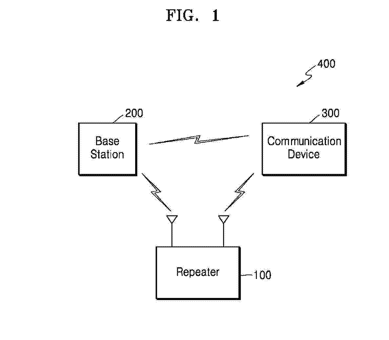
CROSS-REFERENCE TO RELATED APPLICATION[0001]This application claims the benefit of Korean Patent Application No. 10-2015-0190842, filed on Dec. 31, 2015, in the Korean Intellectual Property Office, the disclosure of which is incorporated herein in its entirety by reference.BACKGROUND[0002]1. Field[0003]The inventive concept relates to a method of attenuating signals of a repeater, and more particularly, to a repeater for preventing excessive power of signals input to the repeater, and a method of attenuating signals of the same.[0004]2. Description of the Related Art[0005]A wireless communication system may include a repeater, a base station, and a communication device. The base station and the communication device may transmit and receive signals each other. The communication device is an electronic device capable of wireless communication such as a mobile phone, a smart phone, or a tablet PC. The repeater may be used when signals between the base station and the communication devi...

Claims


Application Information

Patent Timeline
IPC IPC(8): H04B17/40H04W52/24H04W52/46
CPCH04B17/40H04W52/246H04W52/46H04B17/309H04B7/155
Inventor KWON, NAGWONKIM, HYUNCHAE
Owner SOLID
Learn More