Binary decoders in electronic integrated circuits

Active Publication Date: 2007-10-16
STMICROELECTRONICS PVT LTD
View PDF16 Cites 0 Cited by
  • Summary
  • Abstract
  • Description
  • Claims
  • Application Information

AI Technical Summary

Benefits of technology

[0006]The disclosed embodiments of the invention provide binary decoders requiring fewer transistors, decoders with reduced loading on input signals, reduced size, reduced power consumption, and reduced delay.

Problems solved by technology

This manner of implementation results in a bulky and expensive circuit requiring an undesirably large chip area.
The capacitive loading on the input signals reduces the speed of the operation of the device.

Method used


Image

  • Binary decoders in electronic integrated circuits
  • Binary decoders in electronic integrated circuits
  • Binary decoders in electronic integrated circuits

Examples


Embodiment Construction

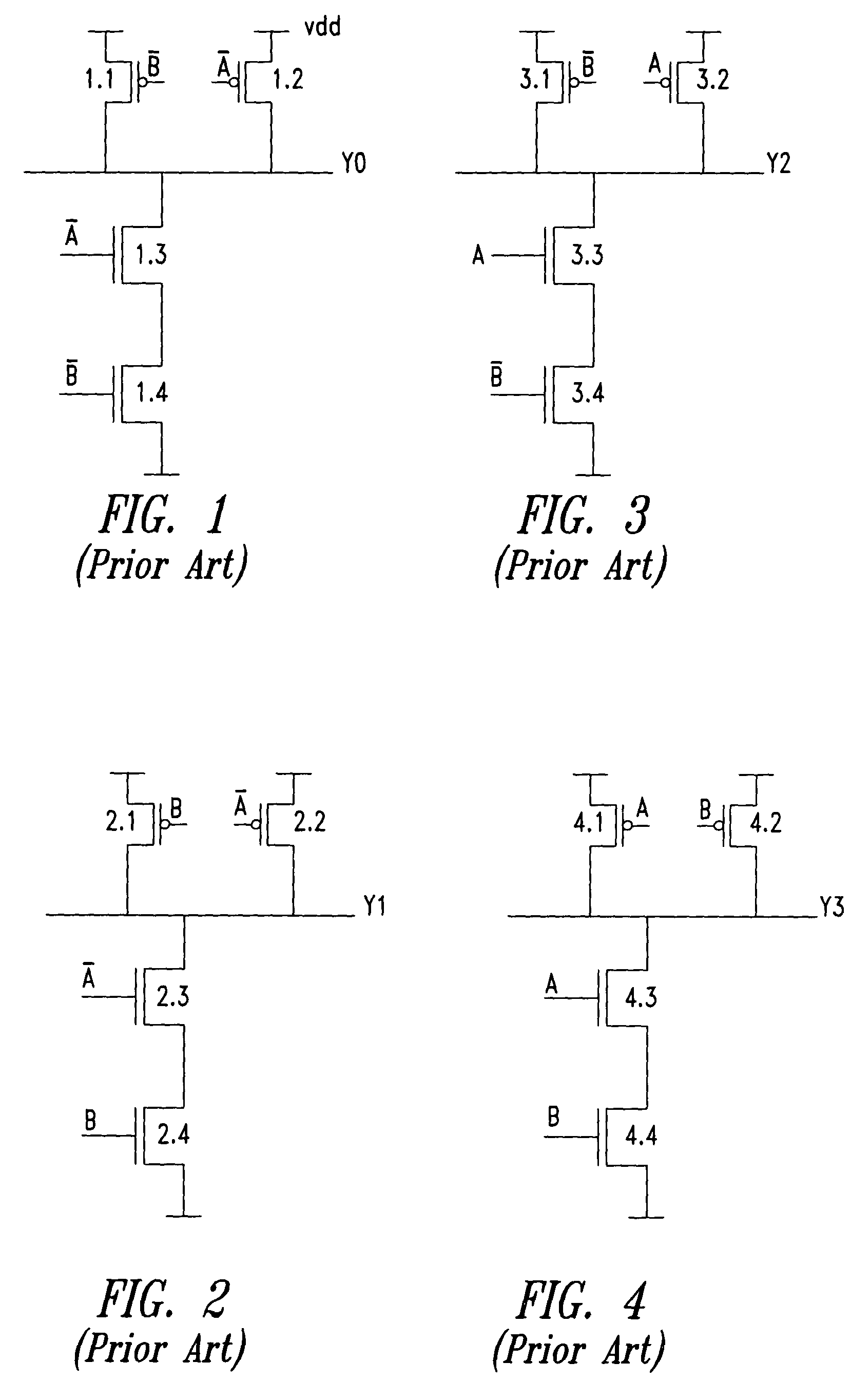
[0021]FIG. 1 shows one circuit of a conventional 2-to-4 decoder, corresponding to a single combination of the inputs= AB or AB. The output Y0 is set to active low whenever this combination is true, i.e., when A=0 and B=0, transistors 1.3 and 1.4 conduct and pull output Y0 to 0. For any other condition Y0 is set to HIGH.

[0022]FIG. 2 shows another circuit of a conventional 2-to-4 decoder, corresponding to another single combination of the inputs=ĀB. The output Y1 is set to active low whenever this combination is true, i.e., when A=0 and B=1, transistors 2.3 and 2.4 conduct and pull Y1 to 0. In any other condition Y1 is set to HIGH.

[0023]FIG. 3 shows another circuit of a conventional 2-to-4 decoder, corresponding to the combination of the inputs=A B, The output Y2 is set to active low whenever this combination is true, i.e., when inputs A=1 and B=0, transistors 3.3 and 3.4 conduct and pull Y2 to 0. In any other condition Y2 is set to HIGH.

[0024]FIG. 4 shows another circuit of a convent...


PUM


Abstract

An improved binary decoder incorporating a selection circuit that activates a selected output corresponding to a input binary value, and a deselecting circuit coupled to each output that deactivates all other outputs when the selected output is activated. The deselecting circuit arrangement has a single input connected to the selected output and a plurality of outputs each of which is connected to one of the remaining outputs and forces them to the inactive state whenever the selected output is activated.

Description

BACKGROUND OF THE INVENTION[0001]1. Field of the Invention[0002]This invention relates to electronic integrated circuits, and in particular to improved binary decoders in integrated circuits.[0003]2. Description of the Related Art[0004]A binary decoder is a circuit that enables a single selected digital output from a defined set of digital outputs, based on an input binary value. The decoder produces an output signal on the single output that matches the input binary value. Binary decoders are essentially combinatorial logic circuits formed by an arrangement of logic gates. A binary decoder having an input value “n” bits is required to have “2n” outputs one of which corresponds with the n-bit value applied at the input. Binary decoders are widely used for performing selection functions where any single device or any single set of devices are required to be selected or enabled from a defined collection of devices or defined collection of device sets. A typical application is in selec...

Claims


Application Information

Patent Timeline
IPC IPC(8): H03M7/00H03M7/16
CPCH03M7/16
Inventor LAL, ABHISHEK
Owner STMICROELECTRONICS PVT LTD
Why Eureka
Try Eureka