

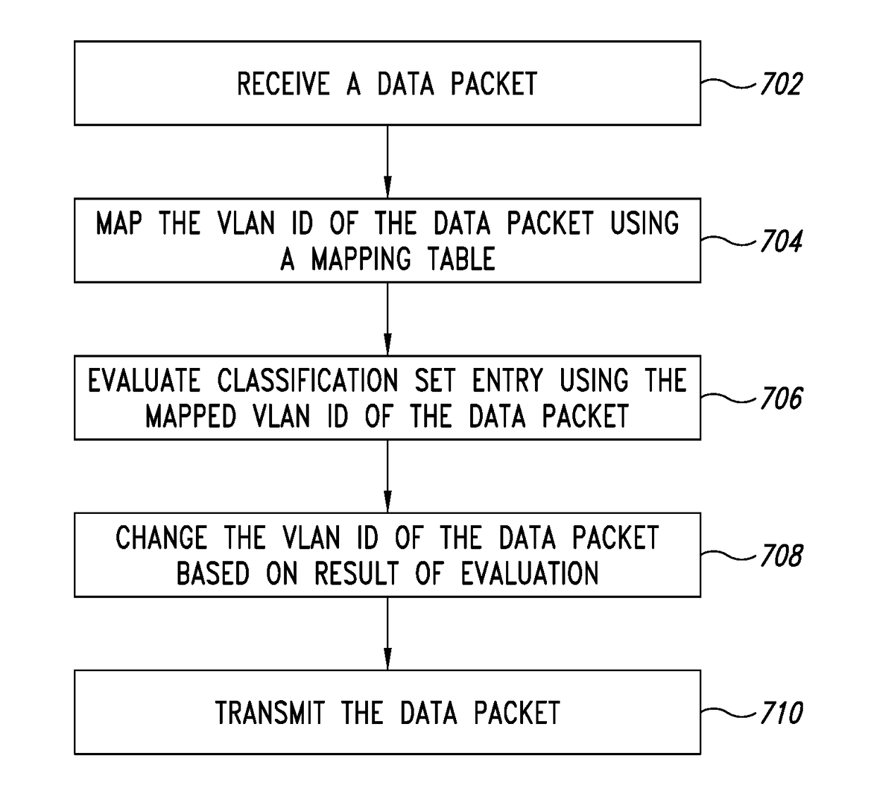
Multipath switching using per-hop virtual local area network classification
a technology of local area network and multi-path switching, applied in data switching networks, digital transmission, electrical equipment, etc., can solve the problems of unfavorable data traffic flow, and inability to prioritize traffic, so as to increase the volume of data trafficked
- Summary
- Abstract
- Description
- Claims
- Application Information
AI Technical Summary
Benefits of technology
Problems solved by technology
Method used
Image

Examples
Embodiment Construction
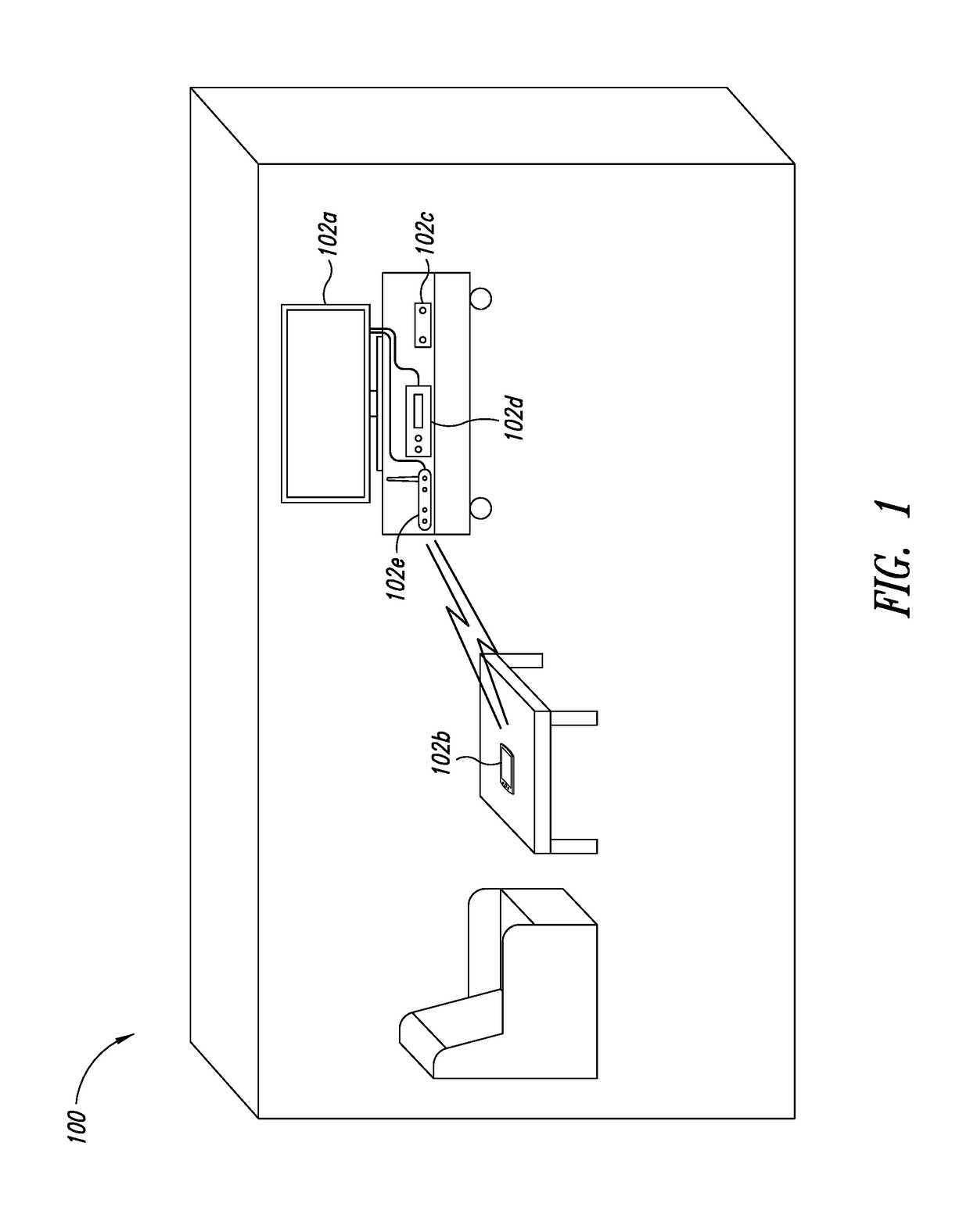
[0015]FIG. 1 shows an environment 100 having a plurality of connected devices 102. The devices 102 may include any type of device 102a that is capable of communicating with another device 102a. In FIG. 1, the plurality of connected devices include a smart television 102a, tablet 102b, set-top box 102c, a receiver 102d and a wireless / wired router 102e. The devices communicate with each other using any type of wireless or wired communication protocol. For example, the devices 102 may communicate using Institute for Electrical and Electronics Engineering (IEEE) 802.3 (also known as Ethernet), IEEE 802.11 (colloquially known as Wi-Fi), IEEE 1901 broadband over power lines (BPL) or the Multimedia over Coax Alliance (MoCA) communication protocol.
[0016]Each device 102 may communicate using one or more different protocols. For example, at one time instance, a device 102 may communicate with another device 102 using IEEE 802.11, whereas at another time instant, the device 102 may communicate...
PUM
 Abstract
Description
Claims
Application Information