Dog clutch and differential gear

a technology of differential gear and dog clutch, which is applied in the direction of mechanical actuated clutches, interengaging clutches, gearing, etc., can solve the problems of increasing the number of components, increasing the size of the device, and increasing the cos

Inactive Publication Date: 2017-07-13
JTEKT CORP
View PDF2 Cites 9 Cited by
  • Summary
  • Abstract
  • Description
  • Claims
  • Application Information

AI Technical Summary

Benefits of technology

[0017]According to the above aspects, it is possib...

Problems solved by technology

On this account, in the differential device configured as described in JP 2003-322240 A, it is necessary to use an electromagnetic coil that can generate a large ...

Method used


Image

  • Dog clutch and differential gear
  • Dog clutch and differential gear
  • Dog clutch and differential gear

Examples


Embodiment Construction

[0028]An embodiment of the present invention will be described with reference to FIGS. 1 to 5C. Note that the embodiment described below shows one preferred concrete example on performing the present invention. There are some parts that specifically exemplify various technical matters that are technically preferable, but the technical scope of the present invention is not limited to such concrete examples.

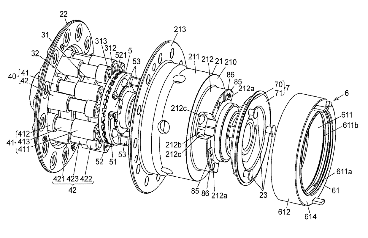
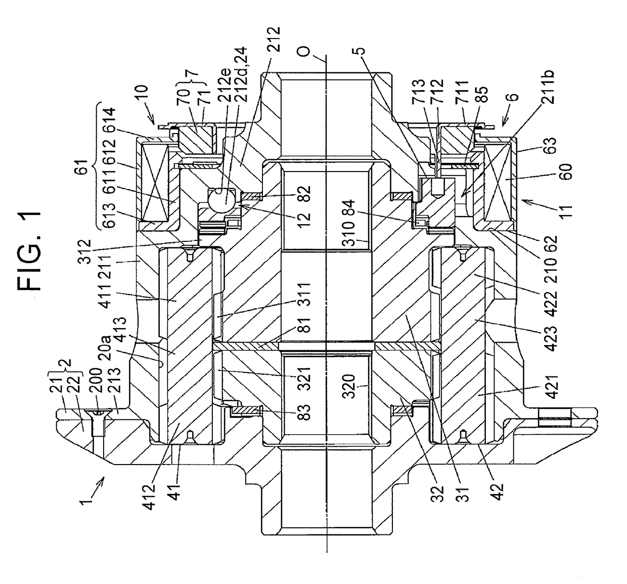
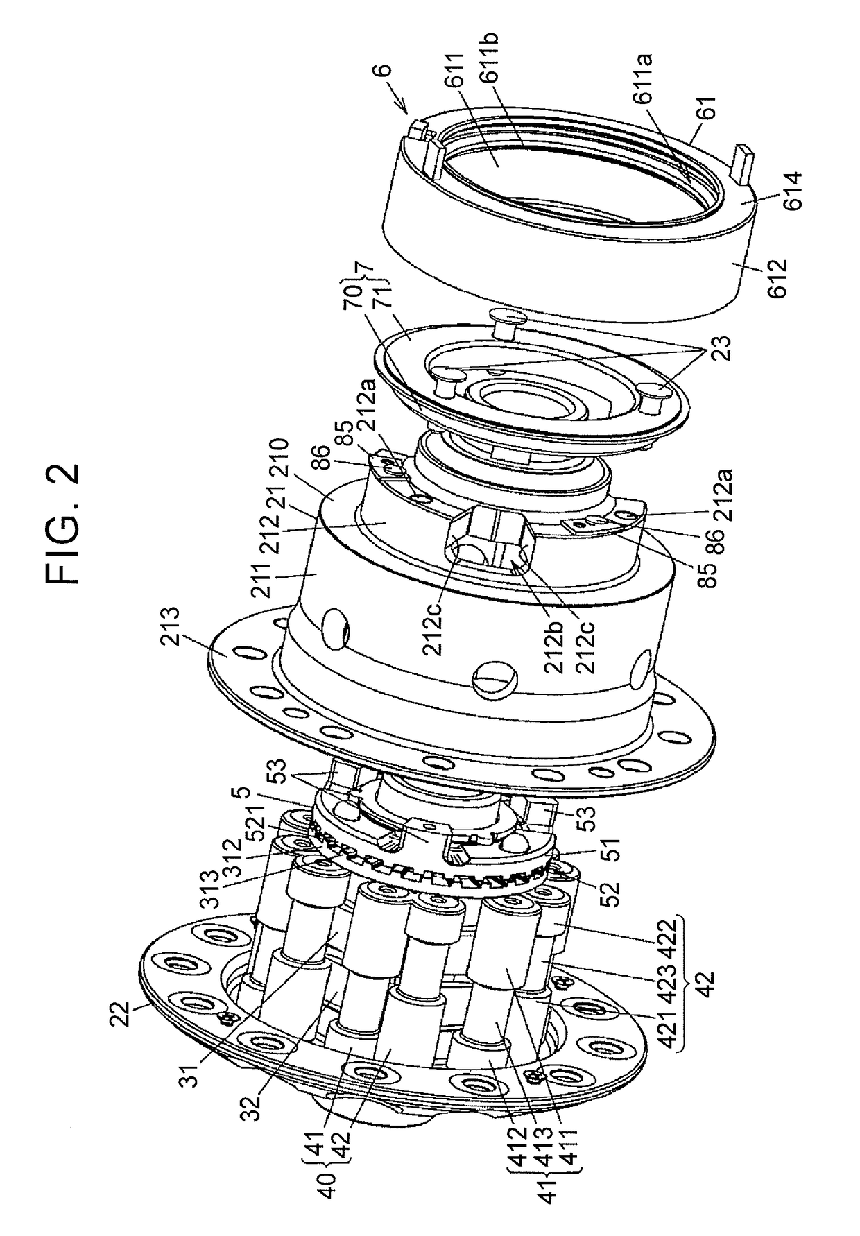
[0029]FIG. 1 is a sectional view illustrating an exemplary configuration of a differential gear according to the embodiment of the present invention. FIG. 2 is an exploded perspective view of the differential gear. FIGS. 3A and 3B are perspective views of a clutch member constituting a pressing mechanism of the differential gear. FIGS. 4A and 4B are sectional views each illustrating a part of the differential gear in an enlarged manner.

[0030]The differential gear 1 is used to distribute a driving force of a drive source for a vehicle while a differential action between a pair of ou...


PUM


Abstract

A dog clutch includes: a first rotational member; a second rotational member; a clutch member; and a pressing mechanism. The clutch member includes a meshing portion meshing with the second rotational member, an engageable portion circumferentially engaging with an engaged portion provided in the first rotational member, and a cam surface configured to generate a cam thrust in a direction of a rotation axis by a relative rotation with respect to the first rotational member. When the clutch member moves, a depth of meshing with the second rotational member is deepened by the cam thrust, and then the engageable portion engages with the engaged portion, so that the clutch member receives a torque from the first rotational member.

Description

INCORPORATION BY REFERENCE[0001]The disclosure of Japanese Patent Application No. 2016-004253 filed on Jan. 13, 2016 including the specification, drawings and abstract is incorporated herein by reference in its entirety.BACKGROUND OF THE INVENTION[0002]1. Field of the Invention[0003]The present invention relates to a dog clutch that transmits a torque between rotational members by meshing, and a differential gear including the dog clutch.[0004]2. Description of Related Art[0005]Some differential devices (differential gears) that allow a differential action between right and left wheels of a vehicle and distribute a driving force thereto include a dog clutch that restricts a differential action between rotational members that are rotatable relative to each other (for example, see Japanese Patent Application Publication No. 2003-322240 (JP 2003-322240 A), Japanese Patent Application Publication No. 2008-95711 (JP 2008-95711 A)).[0006]A differential device described in JP 2003-322240 A...

Claims


Application Information

Patent Timeline
IPC IPC(8): F16H48/24F16D11/14
CPCF16D11/14F16H48/24F16D23/12F16D27/09F16D2023/123
Inventor ONITAKE, MINORUKAMITANI, YASUNORIYAMAMORI, MOTOYASU
Owner JTEKT CORP
Why Eureka
Try Eureka