Folding step for use with mobility device

a technology for mobility devices and folding steps, which is applied in the direction of step stools, walking aids, physical therapy, etc., can solve the problems of inconvenient placement at the end of the table, and achieve the effects of less ambulatory, less ambulatory, and a bit higher step up

Inactive Publication Date: 2017-07-20
HIGHLANDER INVENTIONS CORP
View PDF30 Cites 8 Cited by
  • Summary
  • Abstract
  • Description
  • Claims
  • Application Information

AI Technical Summary

Benefits of technology

[0003]The invention involves an integral step that is built into or capable of being added to a walker. This adds functionality to the walker where a person who needed the step up assistance would not need to have a separate device to do so. This makes it easier for the family and care takers of the individual to assist that person and to move around just one device. The ease of using this encourages outings, thereby improving overall quality of life to the user. The step allows the user of the walker to raise themselves up onto an examining table or into a car, such as an SUV or minivan, while still having the stability of the walker. The step folds into the walker such that it is portable with the walker without interfering with the primary use of it. The folding action of the step brings down a supporting leg portion where a substantial portion of the weight is carried. When the step is moved to the stored position, a linkage moves the supporting portion out of the way. By locating the step to the side and not the front, the step does not interfere with the user's legs or knees. Further, the location of the step on the side would not interfere with a folding seat, something that is frequently a part of the walker.

Problems solved by technology

While an examining table may have a step, the location is often inconvenient at the end of the table, or may be too high for some patients.

Method used


Image

  • Folding step for use with mobility device
  • Folding step for use with mobility device
  • Folding step for use with mobility device

Examples


Embodiment Construction

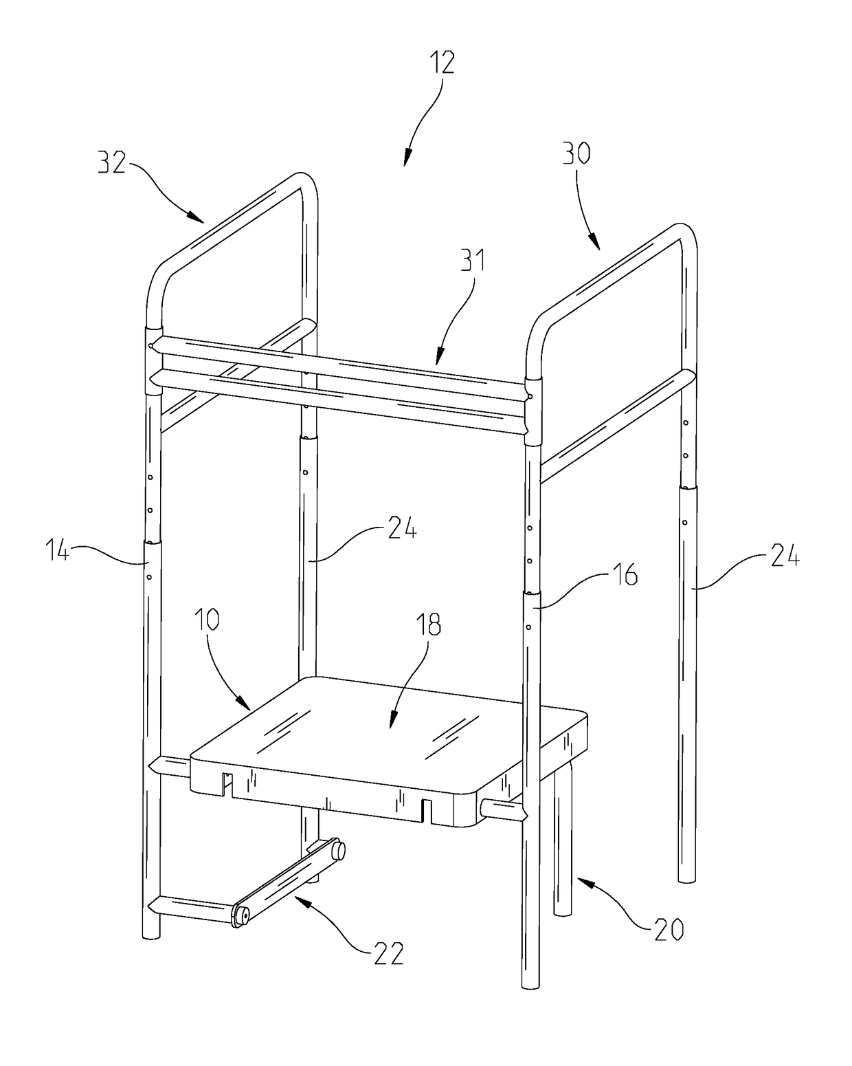
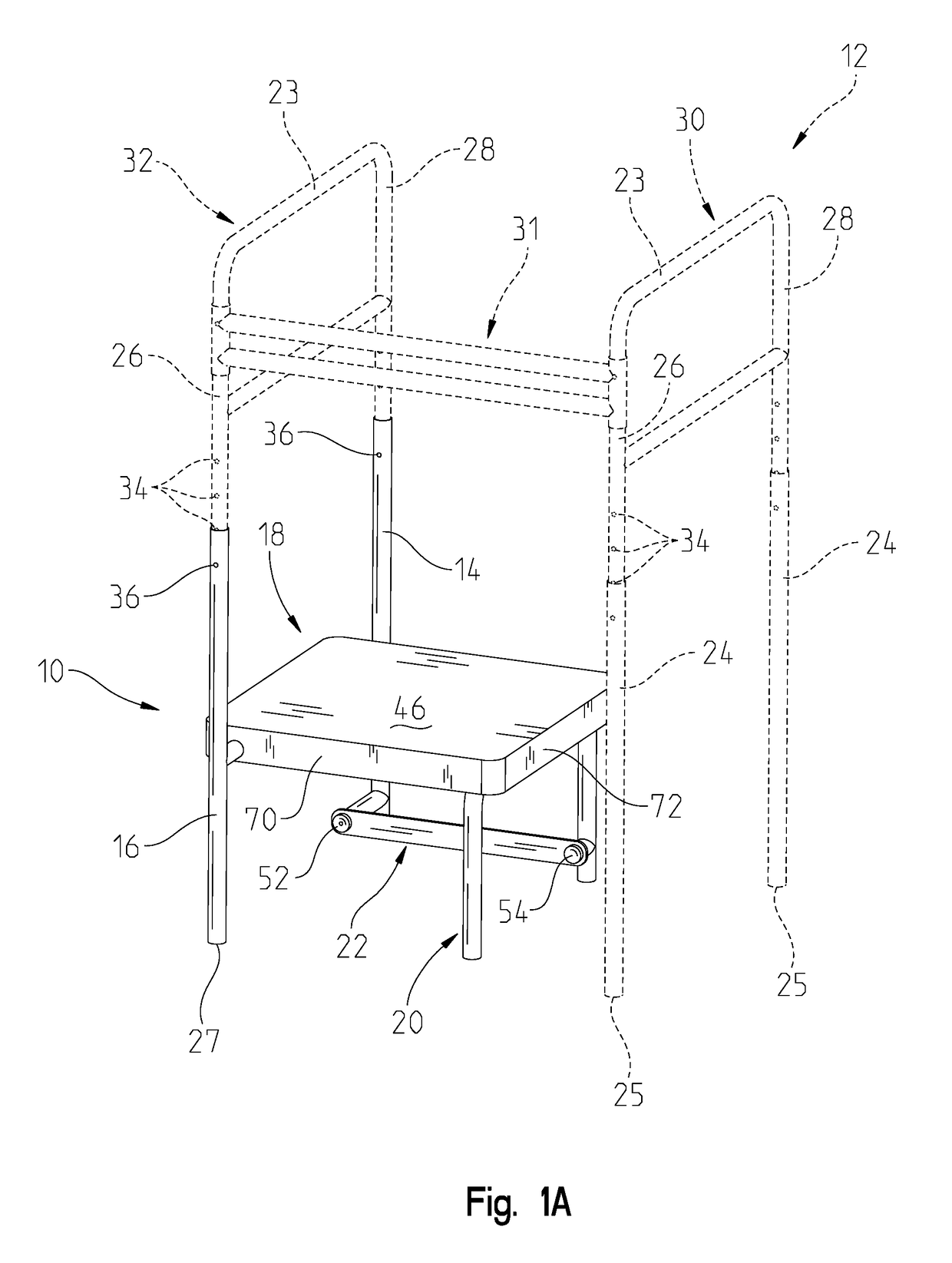
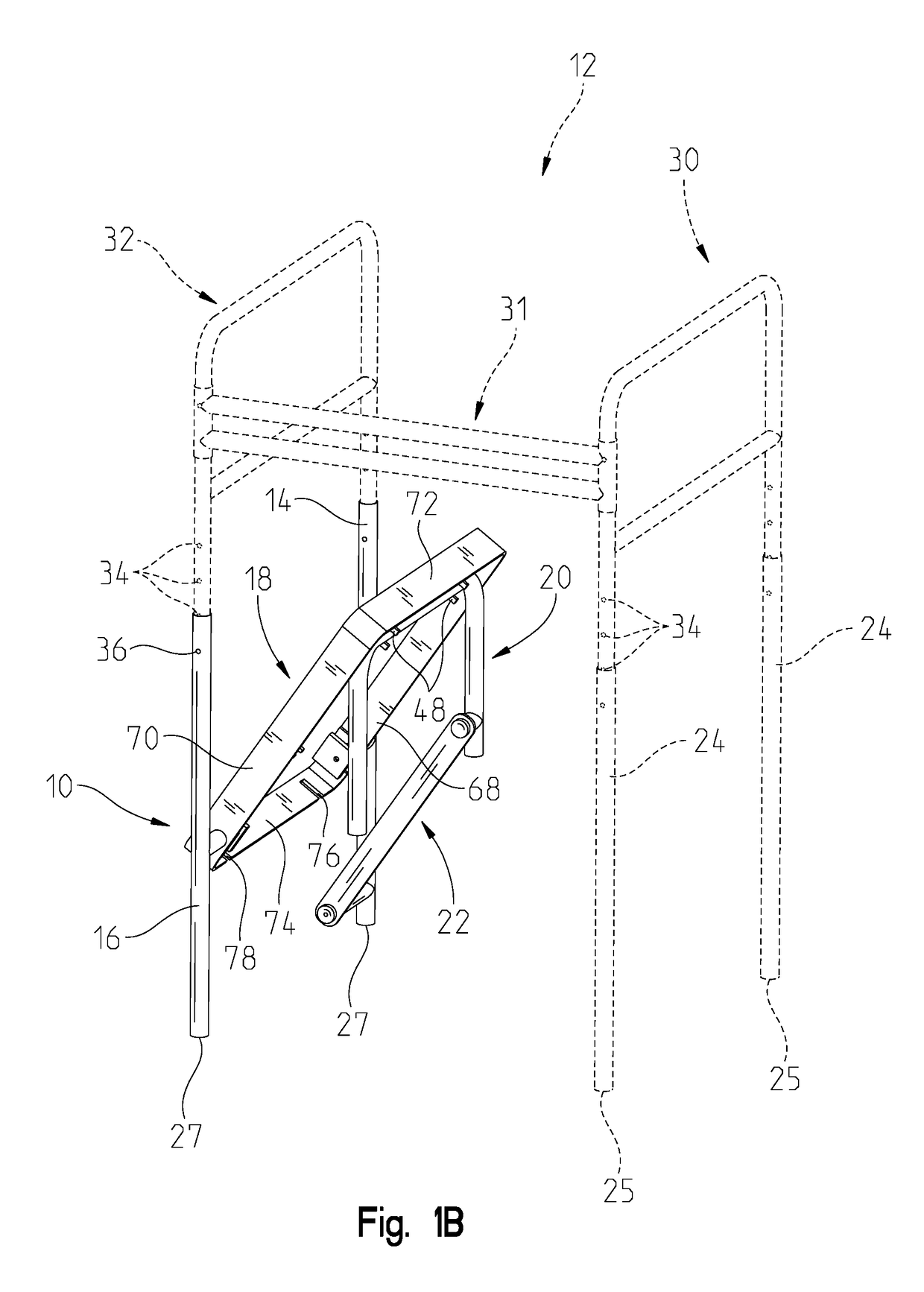
[0022]As shown in FIG. 1A and 1B, a folding step 10 for a walker 12 is composed of a first leg, 16, a second leg, 14, a movable platform 18, a unified leg, 20, and a linkage, 22. The folding step 10 is designed to mate with an existing walker 12, shown in FIG. 1A-1C. The existing walker 12 typically has telescopically adjustable legs 24 that adjust the overall height of the handle portions 23. Specifically, the adjustable legs 24 receive or are received by a front tube portion 26 and a rear tube portion 28. The left side 30 is substantially a mirror image of the right side 32 and the two sides are connected by a front side 31. As shown in FIGS. 1, 2, 5, and 7, the left side 30 has the original adjustable legs 24 that are telescopically moveable to their respective tube portions 26, 28. The adjustable legs 24 have feet 25 that are designed to securely rest on the ground or other horizontal surface. In FIGS. 1A-1C, the right side 32 has the folding step 10 installed, but it is contemp...


PUM


Abstract

A device adapted to be installed on a walker is provided where two of the original adjustable feet are removed from the walker and the device is affixed to the remaining vertical tube portions. The device is affixed to the walker in a similar fashion to the adjustable feet. The device has a platform that moves between a stored position and a use position, the stored position is defined by the platform being up and located between the remaining vertical tube portions and the use position is defined by the step being down, allowing the user to sit or stand on the step. When the platform is up, it allows full access to the space around the walker. A leg is connected to the step where the leg hinges down to support the step.

Description

BACKGROUND OF THE INVENTION[0001]Walkers and other mobility devices are commonly used for people who have difficulty standing, walking, or transitioning between the two. A walker has handles for the user to hang onto and legs that contact the floor and support the handles. Walkers are frequently foldable to become compact, allowing the user to take it with them. This is especially helpful if the user desires to travel. Also, the foldability of the walker allows the user to store it in a closet if the user only needs the walker periodically, such as recovery from surgery or other rehabilitation. At times, the user needs to have a raised step or other load-bearing platform. The current art requires the user to have a secondary device, such as a separate step stool or chair. The secondary device either needs to remain where the user will need it, or be carried around. For people with limited mobility, where moving themselves is difficult or painful, carrying around another device is ou...

Claims


Application Information

Patent Timeline
Patent Type & Authority Applications(United States)
IPC IPC(8): A61H3/04A47C12/00
CPCA47C12/00A61H3/04A61H3/00A61H2003/005A61H2201/0107A61H2201/0161A61H2201/0192
Inventor WEGENER, JOHN ANDREWCONDON, LAURIE ANNE
Owner HIGHLANDER INVENTIONS CORP
Why Eureka
Try Eureka