Electronic mirror device

a technology of mirror device and electronic mirror, which is applied in the direction of identification means, instruments, vehicle components, etc., can solve the problem that the driver cannot monitor the rear view very well through the semi-reflective mirror, and achieve the effect of reducing the visibility of the liquid crystal display, reducing the luminance of the image, and no decrease in visibility

Inactive Publication Date: 2017-07-20
PANASONIC INTELLECTUAL PROPERTY MANAGEMENT CO LTD
View PDF3 Cites 4 Cited by
  • Summary
  • Abstract
  • Description
  • Claims
  • Application Information

AI Technical Summary

Benefits of technology

[0006]According to this configuration, the cholesteric liquid crystal does not reflect but transmits the liquid crystal image circularly polarized by the retarder. This prevents a decrease in the visibility of the liquid crystal display caused by a decrease in the luminance of the image. In addition, since no reflection of the image appears on the cholesteric liquid crystal layer, there is no decrease in visibility due to image overlapping. On the other hand, the cholesteric liquid crystal layer reflects the circularly polarized light coming from the direction opposite the passing circularly polarized light. Accordingly, the cholesteric liquid crystal layer functions as a mirror for outside light. Thus, the electronic mirror device can prevent a decrease in the visibility of the image display unit, which is caused by the conventional semi-reflective mirror.

Problems solved by technology

If rearward visibility is obstructed by a rear seat display or other obstacles, the driver cannot monitor the rear view very well through the semi-reflective mirror.

Method used


Image

  • Electronic mirror device
  • Electronic mirror device
  • Electronic mirror device

Examples


Embodiment Construction

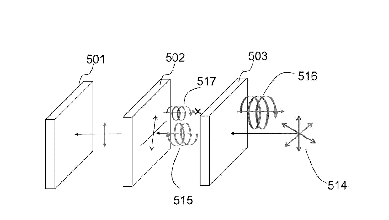
[0017]Prior to describing an exemplary embodiment of the present disclosure, problems with conventional electronic mirror devices will now be briefly described as follows. When the driver sees an image on the image display unit through the semi-reflective mirror, the reflection of the image on the image display unit appears on the image-display-unit side of the mirror. The reflection does not affect the visibility when the driver sees, from the front, the image displayed on the image display unit through the mirror.

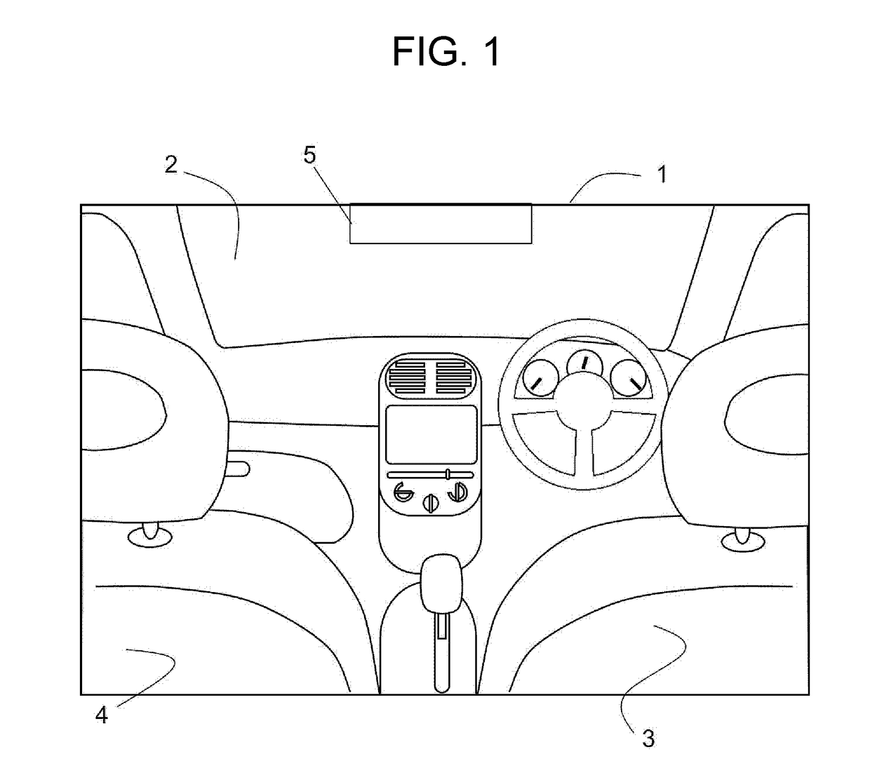
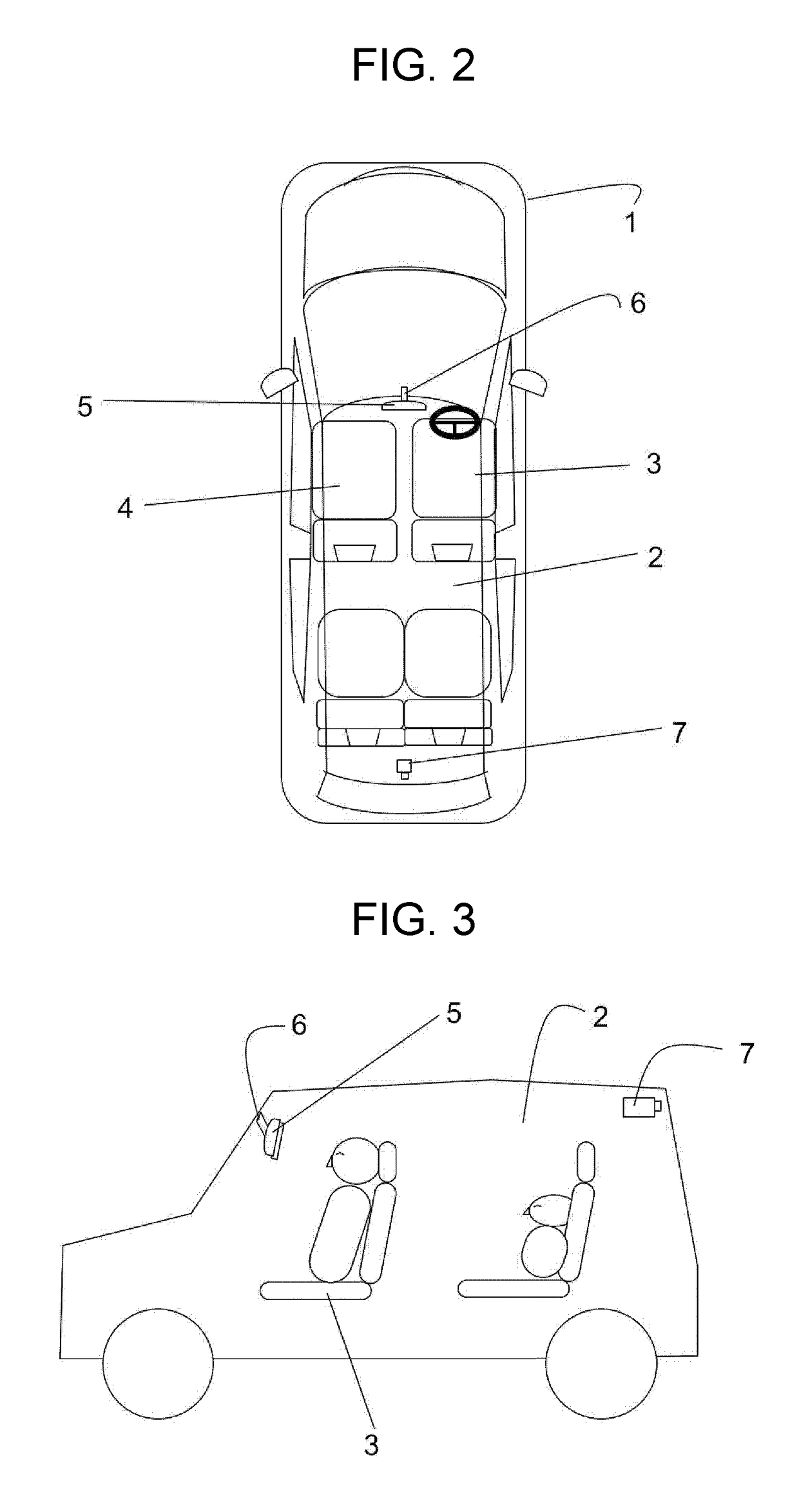
[0018]The image display unit, however, is installed in a position to which a rearview mirror is attached in the automobile interior. As a result, the driver sees the image displayed on the image display unit through the semi-reflective mirror not from the front but at an angle. In that case, the reflection of the image appearing on the image-display-unit side of the mirror causes image overlapping, reducing the visibility of the electronic mirror device.

[0019]In such an e...


PUM

PropertyMeasurementUnit
reflectivityaaaaaaaaaa
luminanceaaaaaaaaaa
luminanceaaaaaaaaaa

Abstract

An electronic mirror device for displaying an image captured by a camera mounted to a vehicle includes a liquid crystal display having a display surface, a retarder, and a cholesteric liquid crystal layer. The retarder is disposed opposite the display surface of the liquid crystal display, and circularly polarizes a liquid crystal image emitted from the liquid crystal display. The cholesteric liquid crystal layer is disposed on the opposite side of the retarder from the liquid crystal display. The liquid crystal image circularly polarized by the retarder passes through the cholesteric liquid crystal layer.

Description

TECHNICAL FIELD[0001]The present disclosure relates to an electronic mirror device which presents the driver with images captured by a camera mounted to an automobile.BACKGROUND ART[0002]Some well-known conventional electronic mirror devices include an image display unit and a semi-reflective mirror that is provided on the front surface of the image display unit. Such electronic mirror devices are useful, for example, in a situation as follows. If rearward visibility is obstructed by a rear seat display or other obstacles, the driver cannot monitor the rear view very well through the semi-reflective mirror. In such a case, an image captured by the camera mounted to the vehicle is displayed on the image display unit, so that the driver can see the image on the image display unit through the semi-reflective mirror so as to monitor the rear view (see, for example, Patent Literature 1).CITATION LISTPatent Literature[0003]PTL 1: Japanese Patent Unexamined Publication No. H11-291817SUMMAR...

Claims


Application Information

Patent Timeline
Patent Type & Authority Applications(United States)
IPC IPC(8): B60R1/00G02F1/137G09F9/35B60R1/04B60R1/12G02F1/13363G02F1/1335
CPCB60R1/00G02F1/13363G02F1/137G02F1/133536B60R1/04B60R1/12B60R2300/8066G02F2001/133638G02F2001/133543G02F2001/133562G02F2201/343B60R2001/1215B60R2300/20G09F9/35G09F9/00G02F1/133509G02F1/133543G02F1/133562G02F1/133638
Inventor OISHI, TOSHIHARU
Owner PANASONIC INTELLECTUAL PROPERTY MANAGEMENT CO LTD
Why Eureka
Try Eureka