Method, computer and magnetic resonance apparatus for planning imaging of a subject that contains an implant

Active Publication Date: 2017-07-20
SIEMENS HEALTHCARE GMBH
View PDF0 Cites 4 Cited by
  • Summary
  • Abstract
  • Description
  • Claims
  • Application Information

AI Technical Summary

Benefits of technology

This patent is about improving magnetic resonance imaging for people who have implants. The issue is that different locations in the body can have different levels of loading during magnetic resonance imaging, so it's important to know where the implant is located and take that information into account when planning the imaging. This approach allows for better estimation of the actual load on the implant and improves the quality of the images obtained. By using position information, the planning process can be optimized and the use of imaging parameters can be restricted only when necessary, ensuring better performance and safety during the magnetic resonance imaging. The position information of the implant can be acquired manually or automatically, depending on the circumstances. Overall, this patent provides a more flexible and efficient way to conduct magnetic resonance imaging for people with implants.

Problems solved by technology

The gradient fields or radio-frequency fields created while magnetic resonance imaging is being carried out can be problematic in relation to such an implant in the examination object.

Method used


Image

  • Method, computer and magnetic resonance apparatus for planning imaging of a subject that contains an implant
  • Method, computer and magnetic resonance apparatus for planning imaging of a subject that contains an implant

Examples


first embodiment

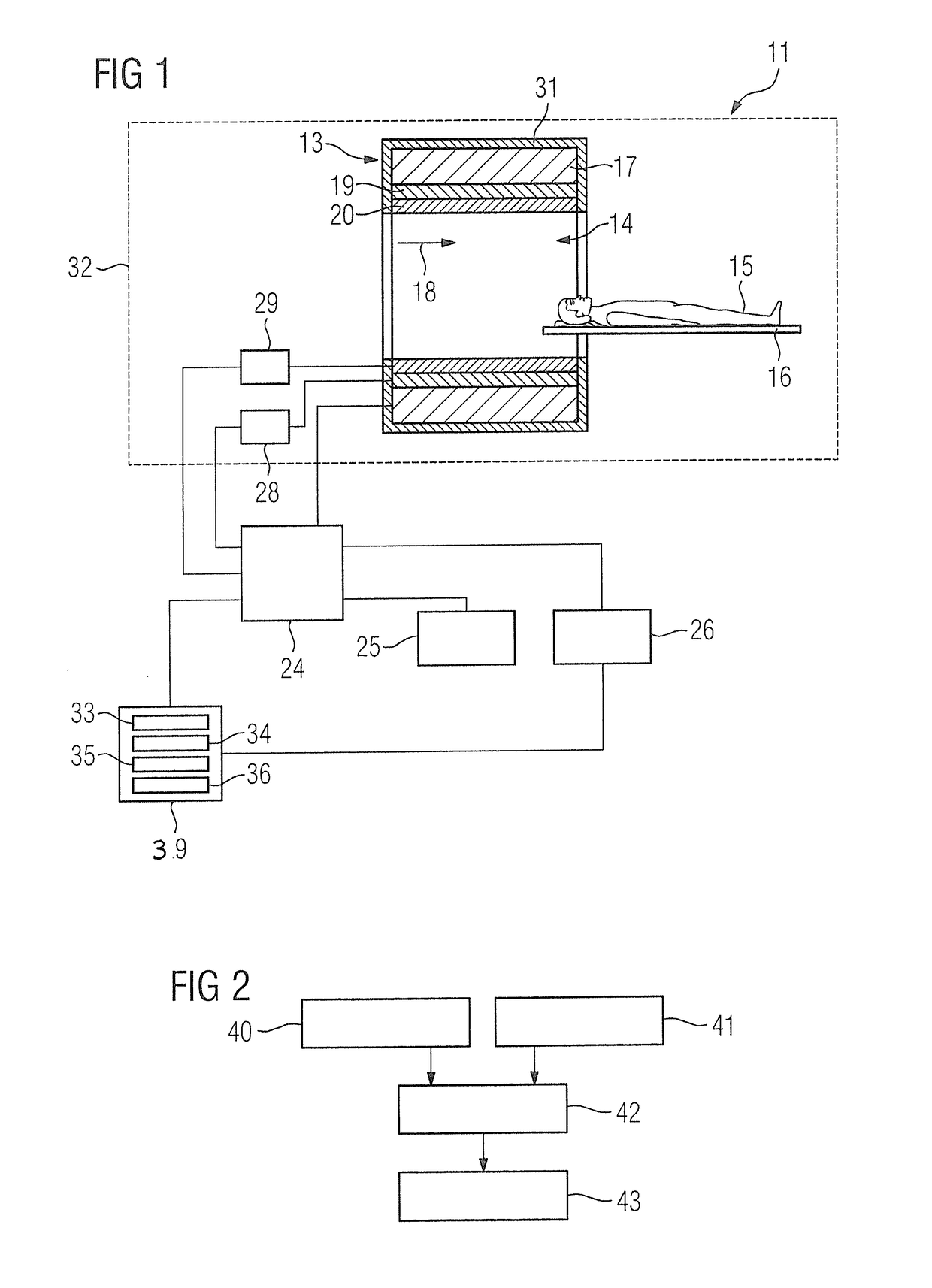
[0070]FIG. 2 is a flowchart of the inventive method for planning magnetic resonance imaging of a body of an examination object 15, wherein an implant is situated in the body of the examination object 15.

[0071]In a first method step 40, position information of the implant is acquired by means of the position acquisition processor 33. This position information characterizes a position of the implant in the body of the examination object.

[0072]In a further method step 41, at least one imaging parameter for the magnetic resonance imaging is predetermined by the predetermination processor 34.

[0073]In a further method step 42, a load parameter of the implant is established on the basis of the acquired position information and the at least one predetermined imaging parameter by the establishment processor 35.

[0074]In a further method step 43, planning of the magnetic resonance imaging on the basis of the established load parameter of the implant is undertaken by the planning processor 36.

second embodiment

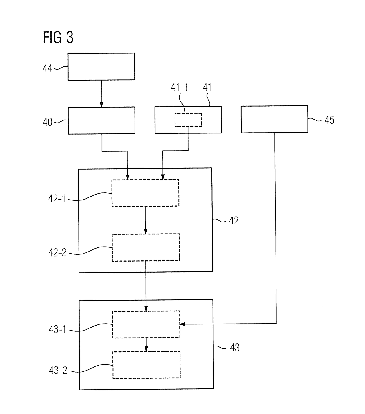
[0075]FIG. 3 is a flowchart of an inventive method for planning magnetic resonance imaging of a body of an examination object 15.

[0076]The description given below is essentially restricted to the differences from the exemplary embodiment in FIG. 2, wherein, as regards method steps, which remain the same, the reader is referred to the description of the exemplary embodiment in FIG. 2. Method steps, which essentially remain the same, are basically given the same reference numbers.

[0077]The embodiment of the inventive method shown in FIG. 3 essentially includes the method steps 40, 41, 42, 43 of the first form of embodiment of the inventive method according to FIG. 2. In addition the form of embodiment of the inventive method shown in FIG. 3 contains additional method steps and substeps. An alternate method sequence to that shown in FIG. 3 is also conceivable, which has only some of the additional method steps and / or substeps shown in FIG. 2. Of course an alternate method sequence to t...


PUM


Abstract

In a method and computer for planning magnetic resonance imaging of a body of an examination object that contains an implant, to be implemented by a magnetic resonance apparatus, position information of the implant is provided to the computer, the position information characterizing a position of the implant in the body of the examination object, and at least one imaging parameter for the magnetic resonance imaging is predetermined before the imaging. At least one load parameter of the implant is established in the computer on the basis of the acquired position information and the at least one predetermined imaging parameter. The magnetic resonance imaging is planned in the computer on the basis of the established load parameter of the implant.

Description

BACKGROUND OF THE INVENTION[0001]Field of the Invention[0002]The present invention concerns a method for planning a magnetic resonance imaging examination of an examination subject that contains an implant, as well as a planning computer for planning such an examination, and a magnetic resonance apparatus and a non-transitory, computer-readable data storage medium for implementing such a method.[0003]Description of the Prior Art[0004]In a magnetic resonance (MR) apparatus, also referred to as a magnetic resonance tomography system, the body of an examination object to be examined, for example a patient, a healthy test subject, an animal or a phantom, is exposed with a basic field magnet system to a relatively high basic magnetic field, for example of 1.5 or 3 or 7 Tesla. In addition, gradient fields are applied with the use of a gradient coil arrangement. Radio-frequency (RF) pulses (excitation pulses), are then radiated by suitable antenna devices via a radio-frequency antenna unit...

Claims


Application Information

Patent Timeline
IPC IPC(8): G01R33/28G01R33/54
CPCG01R33/543G01R33/288G01R33/285
Inventor GRODZKI, DAVID
Owner SIEMENS HEALTHCARE GMBH
Why Eureka
Try Eureka